
Mirror for laser applications and method for manufacture of said mirror

a laser application and mirror technology, applied in the direction of lasers, instruments, laser construction details, etc., can solve the problems of serious decline in the mechanical stiffness and stability of the mirror, adversely affecting the quality of the laser beam focal point and therefore the quality of the processing of the part with the laser, and reducing the heat expansion coefficient. , the effect of improving the thermal stability of the first layer

Inactive Publication Date: 2005-04-12
ROGERS GERMANY
View PDF8 Cites 8 Cited by
  • Summary
  • Abstract
  • Description
  • Claims
  • Application Information

AI Technical Summary

Benefits of technology

Another particular advantage of the present invention is the fact that the mirror has a completely symmetrical design with respect to the consecutive layers that are perpendicular to the mirror surface, which means that changes in temperature cannot cause deformations of the mirror surface. The intermediate layer made of the material with a reduced heat expansion coefficient that is connected directly to the first layer with the mirror surface, not only further improves the thermal stability of the first layer comprising or possessing the mirror surface, but this intermediate layer also especially ensures an even cooling effect on the first layer comprising or possessing the mirror surface. How crucial the mechanical stiffness and stability of a mirror for laser applications is, can be seen from the fact, for example, that even the bending of tubes for the inlet and outlet of coolant can cause changes in the mirror surface, which adversely affects the quality of the laser beam.
is the fact that the mirror has a completely symmetrical design with respect to the consecutive layers that are perpendicular to the mirror surface, which means that changes in temperature cannot cause deformations of the mirror surface. The intermediate layer made of the material with a reduced heat expansion coefficient that is connected directly to the first layer with the mirror surface, not only further improves the thermal stability of the first layer comprising or possessing the mirror surface, but this intermediate layer also especially ensures an even cooling effect on the first layer comprising or possessing the mirror surface. How crucial the mechanical stiffness and stability of a mirror for laser applications is, can be seen from the fact, for example, that even the bending of tubes for the inlet and outlet of coolant can cause changes in the mirror surface, which adversely affects the quality of the laser beam.
Use of the DCB technology prevents solder layers between the individual copper layers. This is essential not only for preventing corrosion, but also creating fine structures for the structured copper layers, i.e. the layers provided with holes and openings, which produces a high degree of homogeneity in cooling of the mirror surface. Furthermore, the use of the DCB technology also provides a high degree of stability, since there are no solder layers, which can be softer than the copper of the copper layers.
A very essential advantage of the design according to the present invention consists in the fact that the cooler structure, and therefore also the mirror in general, possesses the same stability in both axis directions defining the plane of the mirror surface on the top or mirror surface. This is a prerequisite for proper finishing of the mirror surface. The same stiffness of the mirror in both spatial axes defining the mirror surface is achieved by the fact that the cooler structure consists of the copper layers that are stacked one above the other and connected on the surface which each other and that are structured, i.e. provided with openings, instead of using groove-shaped cooling channels.
Moreover, the DCB technology improves the ability to process the copper during manufacture of the mirror surface, i.e. texturing of the copper is achieved, which enables significantly more even treatment of the surface.
The manufacture of the mirror surface in the present invention is achieved by suitable finishing of the top of the first layer facing away from the cooler structure, preferably by means of machining using a tool with a defined cutter, and thereby preferably by means of a diamond tool. The suitable process is also known as diamond turning.

Problems solved by technology

Miniscule alterations and / or deformations, such as warping of the mirror surface in the sub-micrometer range already cause a serious decline in the beam quality of the laser beam reflected on the mirror, especially a decline in the shape or diameter of the beam and the quality of the laser beam focal point or focus on a surface of the part to be processed.
Furthermore, minimal deformations of a mirror surface cause significant operating time differences in the laser beam, thus also adversely affecting the quality of the laser beam focal point and therefore the quality of the processing of the part with the laser.
All of these suggestions are unsatisfactory.
The disadvantage is the complex and also non-symmetrical design of the mirror, so that the axis direction is perpendicular to the mirror surface, causing thermal deformations (bimetal effect).
Another disadvantage is that the individual stays of the plate forming the cooler structure connect directly to the layer possessing the mirror surface without an additional intermediate layer, which causes uneven cooling and therefore deformations of the mirror surface.
A final disadvantage of the known mirror is that it has a high material mass, which is undesirable for laser mirrors that are moved for processing of parts.
The groove-like cooling channels used also have the disadvantage that the stiffness of the mirror on the mirror surface in the longitudinal direction of the grooves is greater than in the transverse direction.
In the necessary finishing of the mirror surface, for example by means of milling with a diamond tool, this causes structures to be formed in the mirror surface due to the varying stiffness, which also adversely affects the beam quality.
This is a disadvantage of all known mirrors that use cooling channels that extend parallel to the mirror surface.
For the cooling of this known mirror, however, there is no cooler structure with connections for the inlet and outlet of a coolant, i.e. the mirror is not connected to an external coolant circuit.
The disadvantage of this known construction is again the lack of symmetry in the direction perpendicular to the mirror axis, especially also of the cooler structure, in addition to the manufacturing expense.
Moreover, the stays limiting the cooling channels of this known mirror likewise extend directly to the layer possessing the mirror surface, so that no homogeneous cooling of the mirror surface is achieved, which means that thermal deformations and faults in the mirror surface are unavoidable.
The disadvantage here is likewise the very complex and therefore expensive construction in addition to the lack of a symmetrical design.
The disadvantage of this known cooler is likewise a complex and expensive design.
Since the spacers are directly connected with the layer forming the mirror surface, no homogeneous cooling of the mirror surface is achieved.
The disadvantages here include the high weight of the mirror, making it unsuitable for a large number of applications.
Moreover, there is no symmetrical design.

Method used


Image

  • Mirror for laser applications and method for manufacture of said mirror
  • Mirror for laser applications and method for manufacture of said mirror
  • Mirror for laser applications and method for manufacture of said mirror

Examples


Embodiment Construction

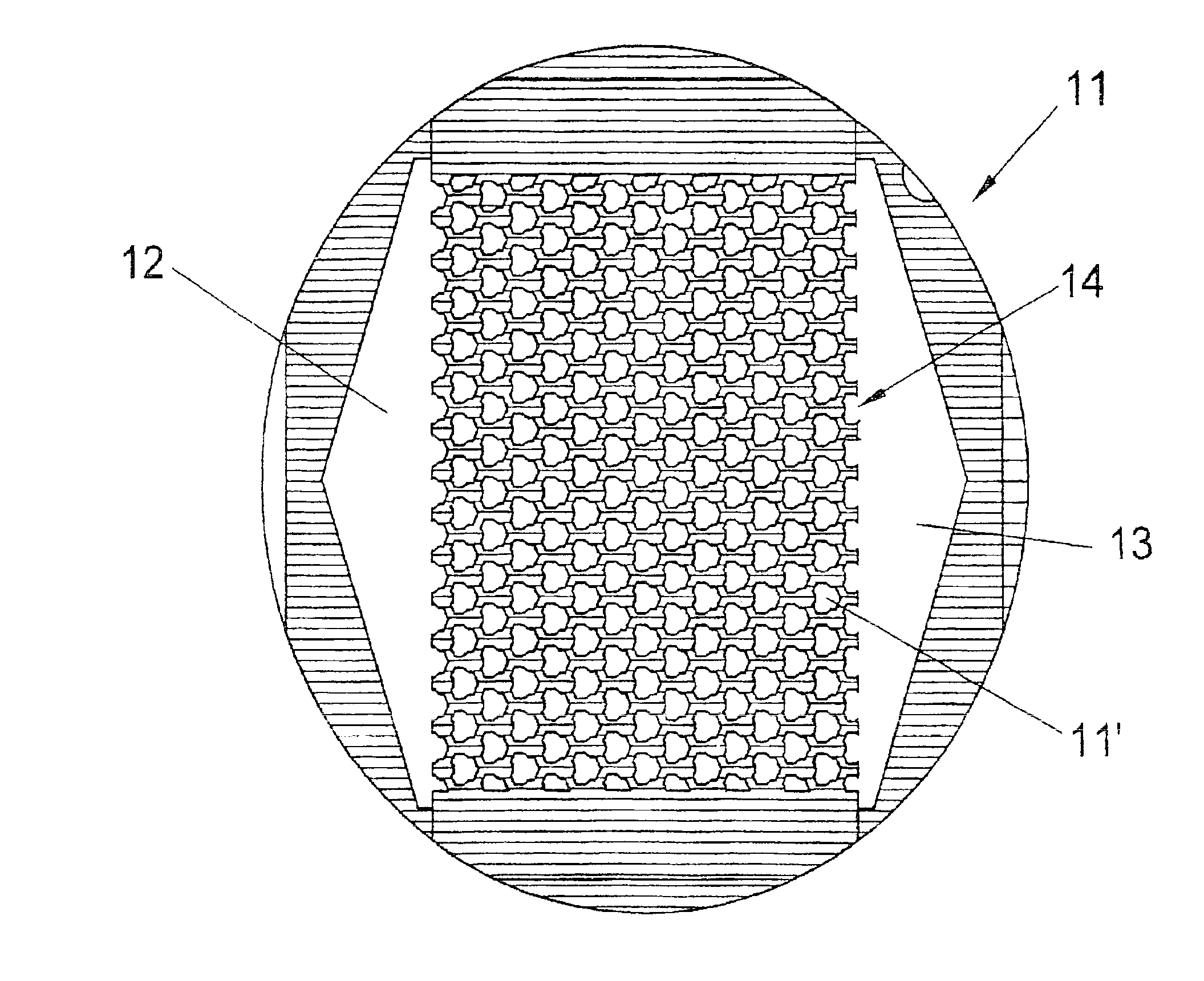
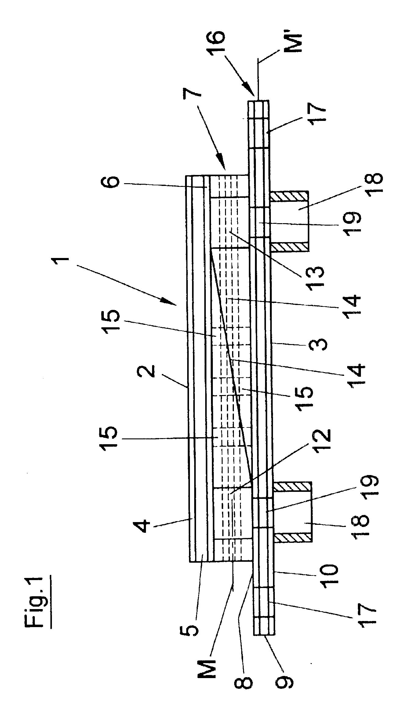
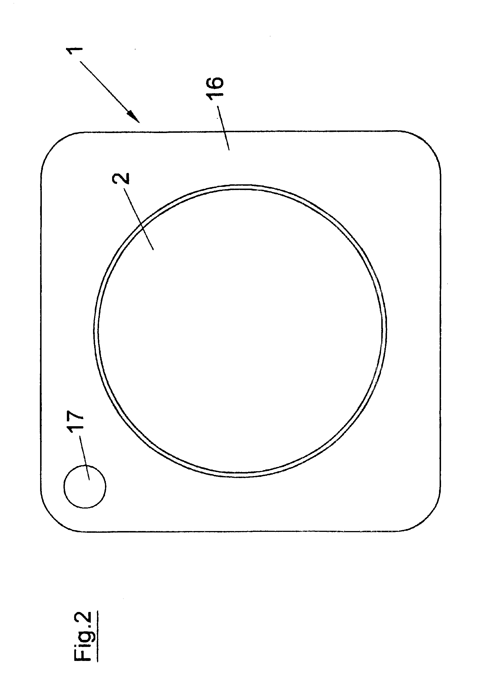
The mirror generally designated 1 in the figures is intended for use in high-energy lasers, for reflecting the laser beam. The mirror 1 is constructed of several layers that are connected with each other on the surface in a suitable manner. In particular, the mirror 1 has the design described below, where the various areas and layers are connected with each other beginning from the top 2 of the mirror toward the bottom 3 of the mirror in the following order:

top copper layer 4 that forms the mirror surface on its open top side 2;

intermediate layer 5;

top copper or end layer 6 for the cooler structure 7 located beneath;

bottom copper or end layer 8 for the cooler structure 7;intermediate layer 9;bottom copper layer 10 that forms the bottom 3 of the mirror 1.

The intermediate layers 5 and 9 are made of a material that has a much lower heat expansion coefficient than the copper of the copper layers, namely equal to or less than 10×10−6[1 / K]. The intermediate layers 5 and 9 are preferably m...


PUM


Abstract

A mirror for laser application and a method for manufacturing the mirror is disclosed herein. The mirror comprises several layers including a top layer used as the mirror surface. A cooling structure including a plurality of cooler layers are providing between the top layer, several intermediate layers and a bottom layer. Connections are provided for allowing a coolant to flow within the mirror. The mirror is constructed by stacking the layers on top of one another and connecting adjacent layers together by direct copper bonding or active soldering.

Description

BACKGROUND OF THE INVENTION1. Field of the InventionThe present invention refers to a cooled mirror for laser applications and in particular to a cooled mirror with a mirror body having a mirror surface and comprising several layers with their surfaces connected in a stack-like arrangement and forming a cooler structure with connections for the inlet and outlet of a coolant, whereby a first layer forming the top of the mirror contains or forms the mirror surface. The present invention refers also to a method for the manufacture of the said cooled mirror for laser applications.2. Description of the Prior ArtIn laser devices, for example in such devices used for processing parts, mirrors are generally needed for reflecting the laser beam, and are moved by a drive for processing of a part. Although the laser beam is generally sent as a widened beam to the mirror used in order to reduce the power density, it is common practice to actively cool such mirrors, using a coolant that flows th...

Claims


Application Information

Patent Timeline
IPC IPC(8): G02B7/18H01S3/04H01S3/08
CPCG02B7/1815H01S3/08059H01S3/0401
Inventor EXEL, KARLKUGLER, LOTHARMEYERSCHULZ-HARDER, JURGENSCHMIDT, KARSTEN
Owner ROGERS GERMANY
Learn More