Safety syringe needle device with interchangeable and retractable needle platform
a safety device and needle platform technology, applied in the direction of packaging foodstuffs, packaged goods types, pharmaceutical containers, etc., can solve the problems of affecting the safety of disposed materials, and causing needle stick injuries to maintenance personnel who handle disposed materials, so as to eliminate the occurrence of needle stick injuries
- Summary
- Abstract
- Description
- Claims
- Application Information
AI Technical Summary
Benefits of technology
Problems solved by technology
Method used
Image
Examples
first embodiment
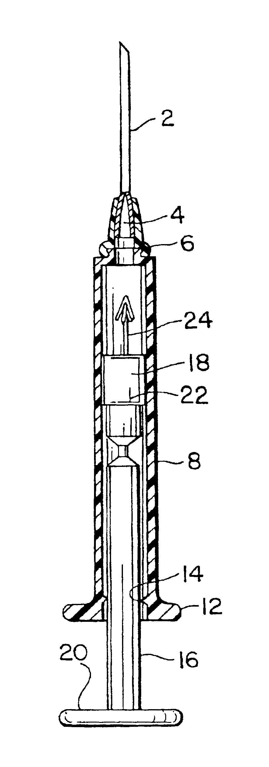
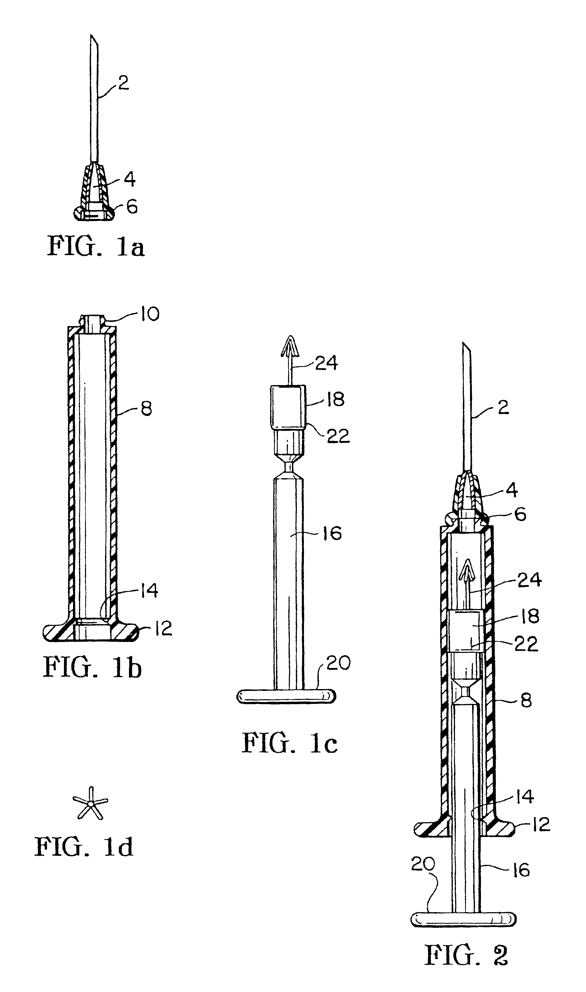
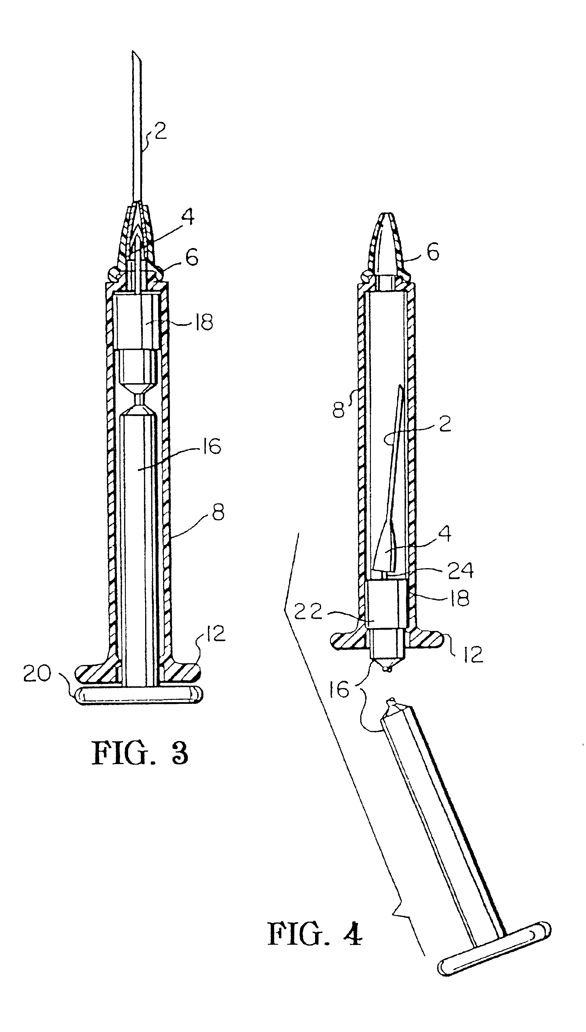
Referring to the drawings, FIGS. 1a, 1b and 1c illustrate the three basic components which make up the novel needle retractable syringe. FIG. 1a illustrates in side elevation partial section view the construction and interaction of the needle 2 and cup 4 which fits detachably within the interior of hub 6 of the syringe. Hub 6 has a female thread in the base of its interior. FIG. 1b illustrates in side elevation partial section view the construction and interaction of the barrel 8, the partially closed threaded hub receiving end 10, which is located at the top of the barrel 8, and the barrel base 12 which is formed at the bottom of the barrel 8. A circular rim-like catch 14 is formed in the interior of the barrel 8 immediately above the barrel base 12 and provides a stop to deter full withdrawal of the plunger 16 from the interior of the barrel 8. Alternatively the needle may during manufacture be affixed integrally to the syringe base and be removable only during retraction into the...
second embodiment
FIG. 8 illustrates a side elevation partial-section view of the syringe which is constructed to have a screw-lock plunger-needle hub connection. As can be seen in FIG. 8, the barrel 8 has the syringe plunger 16 disposed therein. The plunger 16 carries at its frontal end (the left end as seen in FIG. 8) a piston 26 which is constructed of a resilient material such as resilient rubber so that it snugly engages the inner cylindrical surface of the barrel 8. The piston 26 is connected to the plunger 16 by means of a plunger flange 36. The frontal end of the plunger 16 is constructed to have therein a cylindrical cavity which has a female thread 28 formed in the wall of the cavity. The base of the hub 6 is constructed to have a male hub thread 34, which is formed to match and engage the female thread 28 formed in the opening in the front end of the plunger 16. FIG. 3 also illustrates piston stop 15 formed in the rear end of the interior of the barrel 8 (the right side as seen in FIG. 8)....
PUM
 Abstract
Description
Claims
Application Information
 - R&D
- Intellectual Property
- Life Sciences
- Materials
- Tech Scout
- Unparalleled Data Quality
- Higher Quality Content
- 60% Fewer Hallucinations
Browse by: Latest US Patents, China's latest patents, Technical Efficacy Thesaurus, Application Domain, Technology Topic, Popular Technical Reports.
© 2025 PatSnap. All rights reserved.Legal|Privacy policy|Modern Slavery Act Transparency Statement|Sitemap|About US| Contact US: help@patsnap.com


