Connection between a waveguide array and a fiber array

Inactive Publication Date: 2005-04-12
HO SENG TIONG
View PDF20 Cites 60 Cited by
  • Summary
  • Abstract
  • Description
  • Claims
  • Application Information

AI Technical Summary

Benefits of technology

The present invention provides an improved connection between an optical fiber or optical fiber array and an integrated optical waveguide or integrated optical waveguide array mounted or fabricated on a grooved substrate. According to an aspect of the present invention, an end face of an optical fiber array is shaped to have a first facet and a second facet. The first facet has an inclination angle that is substantially equal to the inclination angle of an end wall of the substrate groove, and the second facet

Problems solved by technology

In general, however, the addition of such stops and structures complicates the fabrication of the waveguide and the positioning and alignment of the optical fiber.
But becau

Method used


Image

  • Connection between a waveguide array and a fiber array
  • Connection between a waveguide array and a fiber array
  • Connection between a waveguide array and a fiber array

Examples


Embodiment Construction

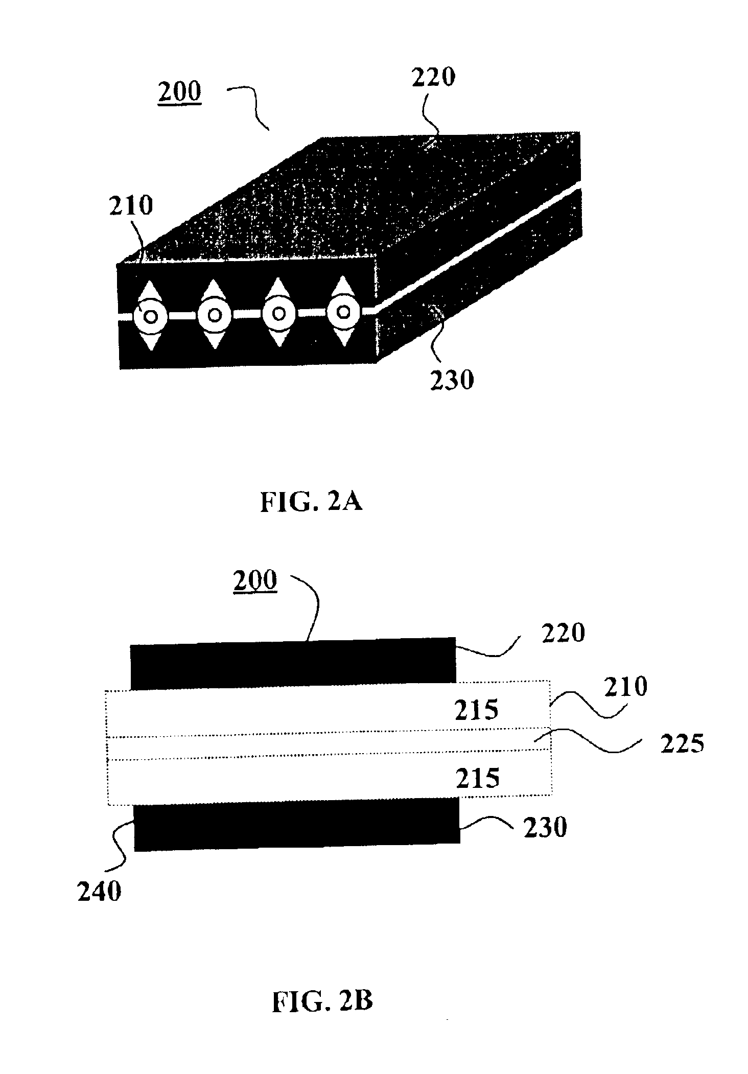
FIGS. 2A and 2B show a three-dimensional view and a side view, respectively, of an exemplary embodiment of a fiber array 200. Fiber array 200 comprises first and second grooved chips 220, 230, which may be made from silicon or other material using any suitable fabrication technology, such as wet etching. Depending on the diameter of the fiber and the desired height of the fiber central axis relative to the chip surface (for instance, 5 μm above the surface), etching parameters for fabricating the grooves may be selected, as is well known in the art. The grooves may be V-grooves as shown, or they may have a U-shaped or other cross section suitable for holding optical fibers in position. One or more optical fibers 210 are sandwiched between first and second chips 220 and 230. The spacing of the fibers in a multi-fiber array is controlled by the spacing of the grooves, which may be selected as desired. The grooved surface of the first chip 220 is treated so as to bond fibers 210 perman...


PUM


Abstract

In a connection between an optical fiber or optical fiber array and an integrated optical waveguide or integrated optical waveguide array mounted or fabricated on a grooved substrate, an end face of an optical fiber array has a first facet and a second facet. The first facet has an inclination angle substantially equal to the inclination angle of an end wall of the substrate groove; the second facet has an inclination angle substantially equal to the inclination angle of the end face of the integrated optical waveguide. When the optical fiber array is mounted on the grooved substrate, each of the fibers rests in one of the substrate grooves. The first facet of each optical fiber end face is aligned with the end wall of the groove in which it rests, and the second facet is aligned with the end face of the integrated optical waveguide.

Description

BACKGROUND OF THE INVENTIONThe invention relates generally to fiber optic communications and in particular to systems and methods for coupling optical fibers to integrated optical waveguides.As fiber-optic communication advances to handling larger bandwidth, photonic integrated circuits or chips are expected to replace many of the discrete optical components that are currently used to construct optical communication systems. In systems combining optical fibers and photonic integrated circuits, light must be efficiently coupled between optical fibers and integrated optical channel waveguides. A practical coupling setup must be reliable, efficient, and capable of mass production at low per-unit cost.Existing techniques for fixing an optical fiber (and lens) in position with respect to a channel waveguide include epoxy curing, soldering, mechanical fixture, and laser welding. In order to reduce the need for manual picking and placing / aligning of components in the packaging process, eff...

Claims


Application Information

Patent Timeline
IPC IPC(8): G02B6/30G02B6/36G02B6/42
CPCG02B6/30G02B6/3636G02B6/423G02B6/3692G02B6/4212G02B6/3652
Inventor ZHOU, YANCHENG, SHIDEHO, SENG-TIONG
Owner HO SENG TIONG
Why Eureka
Try Eureka