
Detecting the endpoint of a chamber cleaning

Inactive Publication Date: 2005-04-19
APPLIED MATERIALS INC
View PDF3 Cites 12 Cited by
  • Summary
  • Abstract
  • Description
  • Claims
  • Application Information

AI Technical Summary

Benefits of technology

[0019]An advantage of the invention is that a significantly reduced amount of cleaning gas is necessary to clean a chamber because only the amount of NF3 actually necessary to clean the chamber is used. Less waste of costly NF3 occurs because real-time monitoring of the cleaning is employed. It is another advantage that the endpoint of a chamber cleaning can be determined. For at least these reasons, the cleaning process is less costly than prior methods. Finally, problems with manometer drift and recipe timeout are substantially eliminated.
is that a significantly reduced amount of cleaning gas is necessary to clean a chamber because only the amount of NF3 actually necessary to clean the chamber is used. Less waste of costly NF3 occurs because real-time monitoring of the cleaning is employed. It is another advantage that the endpoint of a chamber cleaning can be determined. For at least these reasons, the cleaning process is less costly than prior methods. Finally, problems with manometer drift and recipe timeout are substantially eliminated.

Problems solved by technology

During subsequent depositions, the film on the walls, etc., can crack or peel, causing contaminant particles to fall on the substrate.
This causes problems and damage to particular devices on the substrate.
Damaged devices have to be discarded.
The presence of contaminates in the processing chamber is even more serious in this case, since the computer screen and the like will be inoperative if damaged by particulates.
This technique is vulnerable to, e.g., variations in the manometer pressure reading over time, i.e., “manometer pressure drift”.
Even though the chamber is cleaned, throughput is reduced and cost increased, the latter especially because NF3 is significantly more expensive than that of any other process gas.
Flowing a large and constant amount of NF3 is costly and inefficient.
On the other hand, if the manometer drifts high, the preset pressure may be attained prior to endpoint, resulting in an incomplete clean.
In this way, the flow rate is no longer constant, decreasing near the endpoint and saving costly NF3.
A drawback of this solution is that the endpoint of the cleaning procedure cannot be detected using the rise of the NF3 level, since its pressure is by design constant.

Method used


Image

  • Detecting the endpoint of a chamber cleaning
  • Detecting the endpoint of a chamber cleaning
  • Detecting the endpoint of a chamber cleaning

Examples


Embodiment Construction

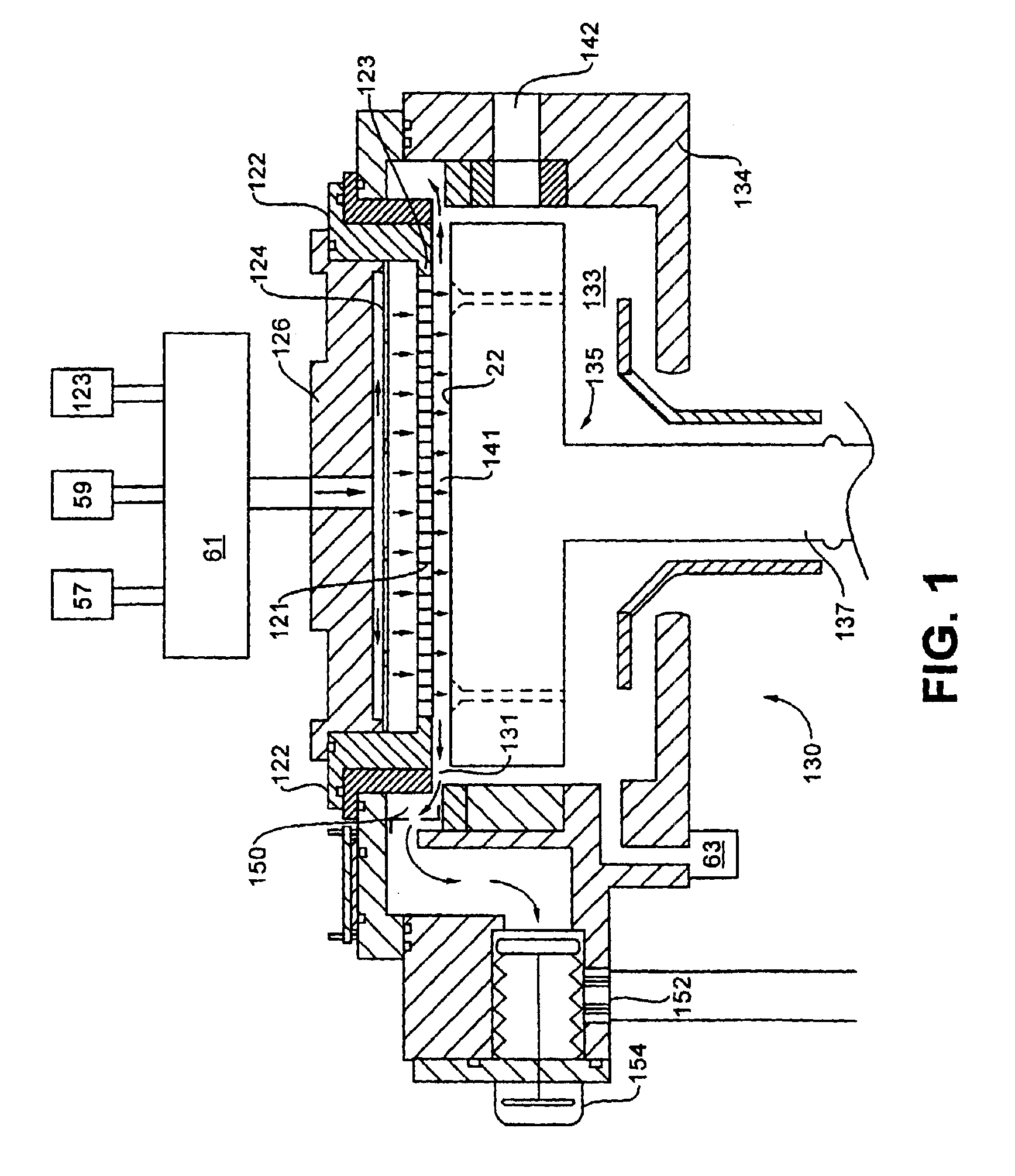
[0027]U.S. Pat. No. 5,366,585, issued Nov. 22, 1994 to Robertson et al., entitled “Method and Apparatus for Protection of Conductive Surfaces in a Plasma Processing Reactor”, assigned to the assignee of the present invention, and incorporated herein by reference, discloses a PECVD chamber with which the present invention may be used. Of course, the invention is applicable to numerous other types of CVD devices as well as devices for other deposition methods.

[0028]As shown in FIG. 1, a PECVD apparatus 130 includes a susceptor 135 having a stem 137. Susceptor 135 is centered within a vacuum deposition process chamber 133. Susceptor 135 holds a substrate such as a glass panel (not shown) in a substrate processing or reaction region 141. A lift mechanism (not shown) is provided to raise and lower the susceptor 135. Commands to the lift mechanism are provided by a controller. Substrates are transferred into and out of chamber 133 through an opening 142 in a sidewall 134 of the chamber 13...


PUM

PropertyMeasurementUnit
Ratioaaaaaaaaaa
Wavelengthaaaaaaaaaa
Threshold limitaaaaaaaaaa

Abstract

A method and apparatus for cleaning a CVD chamber including optoelectronic detection of the completion or endpoint of the cleaning procedure once a ratio of emission lines reaches a threshold value. The method comprises the steps of: providing a plasma of a cleaning gas into the chamber and creating a plasma from the cleaning gas. The intensity of emission lines of the cleaning gas and of at least one background gas in the chamber are monitored. A ratio of the intensity of the cleaning gas emission line to the intensity of the background gas emission line is determined and monitored as a function of time. The determined ratio is compared to a preset threshold calibration value. The flow of gas is controlled based on the comparing step. The apparatus includes a cleaning gas supply with a valved inlet providing an entrance to the interior of the chamber for passing cleaning gas to the interior of the chamber. A detector having an optical input is disposed for sensing the electromagnetic radiation. The detector has a first channel for detecting a relative intensity of an emission line corresponding to the cleaning gas and a second channel for detecting a relative intensity of the emission line corresponding to the background gases. Software or circuitry is employed to determine a normalized signal using a signal from the first channel and a signal from the second channel. The value of the normalized signal is substantially invariant with respect to simultaneous corresponding changes in the intensity of the signal measured by the first channel and the intensity of the signal measured by the second channel.

Description

CROSS REFERENCE TO RELATED APPLICATION[0001]This patent application is a divisional of application Ser. No. 08 / 904,432 filed Aug. 1, 1997, now U.S. Pat. No. 6,534,007.BACKGROUND OF THE INVENTION[0002]The present invention relates generally to chemical vapor deposition (CVD) processing, and more particularly to a method and apparatus for CVD chamber cleaning.[0003]CVD is widely used in the semiconductor industry to deposit films of various kinds, such as intrinsic and doped amorphous silicon (a-Si), silicon oxide (SixOy), silicon nitride (SirNs), silicon oxynitride, and the like on a substrate. Modern semiconductor CVD processing is generally done in a vacuum chamber by using precursor gases which dissociate and react to form the desired film. In order to deposit films at low temperatures and relatively high deposition rates, a plasma can be formed from the precursor gases in the chamber during the deposition. Such processes are known as plasma-enhanced CVD processes or PECVD.[0004]S...

Claims


Application Information

Patent Timeline
IPC IPC(8): C23C16/44H01J37/32C23C14/56H01L21/205
CPCC23C14/564C23C16/4405H01J37/32963H01J37/32862Y10S438/905
Inventor BLONIGAN, WENDELL T.GARDNER, JAMES T.
Owner APPLIED MATERIALS INC
Features
  • Generate Ideas
  • Intellectual Property
  • Life Sciences
  • Materials
  • Tech Scout
  • Unparalleled Data Quality
  • Higher Quality Content
  • 60% Fewer Hallucinations
Learn More