Chain

a technology of chain pins and pins, applied in the field of chains, can solve the problems of limited use of refined pins mentioned above, significant effect of inner and outer plate fatigue fracture, and breakdown of inner and outer link plates, and achieve the effects of enhancing the fatigue fracture limit, enhancing residual compressive stress, and enhancing the fatigue strength of chain pins

Inactive Publication Date: 2005-04-19
SUGIYAMA CHAIN
View PDF5 Cites 14 Cited by
  • Summary
  • Abstract
  • Description
  • Claims
  • Application Information

AI Technical Summary

Benefits of technology

[0012]Dimples with a size smaller than that of the dimples mentioned above are also formed on the surface of the chain pins which have undergone the hard shot peening (primary shot peening) by means of secondary shot peening performed at an arc height value smaller than that of the shot peening mentioned above. The use of steel balls deposited with iron-zinc alloy as a projecting medium for carrying out the secondary shot peening allows iron-zinc alloy coating film to be formed on the dimples with a size smaller than that of the dimples mentioned above.
[0013]The chain according to the present invention is provided with the increased residual compressive stress through primary shot peening that results in an enhancement in fatigue strength of the chain pins. Such pins are able to withstand a bending moment caused by tensile loads and enhance the fatigue fracture limit of the inner and outer link plates so that the maximum allowable load of the chain can be significantly increased. If the maximum allowable load may be comparable to that of the prior art, a one size smaller chain is acceptable, thereby achieving downsizing and weight saving.
[0014]In addition, the surface of the chain pins can be smoothened to as the highest degree as possible and can have a greater hardness by applying the secondary shot peening to the chain pins to downsize the dimple described above by forming an iron-zinc alloy coating film layer on the dimples which are formed by means of the secondary shot peening. This results in reduction in friction resistance that occurs between the chain pins and the bushings, and thereby improving in the durability of the chain.

Problems solved by technology

With such steel chain, when components thereof reach durability limits due to repeated uses for an extended period of time, fatigue first occurs in the inner and outer link plates so that flexure deformation of the chain pin has a significant effect on fatigue fracture of the inner and outer plates.
These result in breakdown of the inner and outer link plates 11, 12 due to accumulation of fatigue therein.
However, the use of refined pins mentioned above is limited to a chain which is used a small number of repetitions at low speed and with a heavy load, since it has high creep rupture strength against impact loads, but low fatigue strength.
However, with a chain using the refined pins, not much satisfactory fatigue strength has been obtained as compared to a number of man-hours for production and the production costs.
Shot peening mentioned above serves as a soft shot for cleaning and finishing the surface of the parts through an approach such as removing the oxide coating film which are formed through heat treatment, and has not provided a maximum enhancement of fatigue strength.
If the pin 15 and the bushing 13 are in a slide contact with each other for a long period of time, a clearance therebetween is widened due to sliding wear, thereby resulting in a stretched chain which is caused by accumulation of sliding wear between the chain pin and the bushing.

Method used


Image

  • Chain
  • Chain
  • Chain

Examples


first embodiment

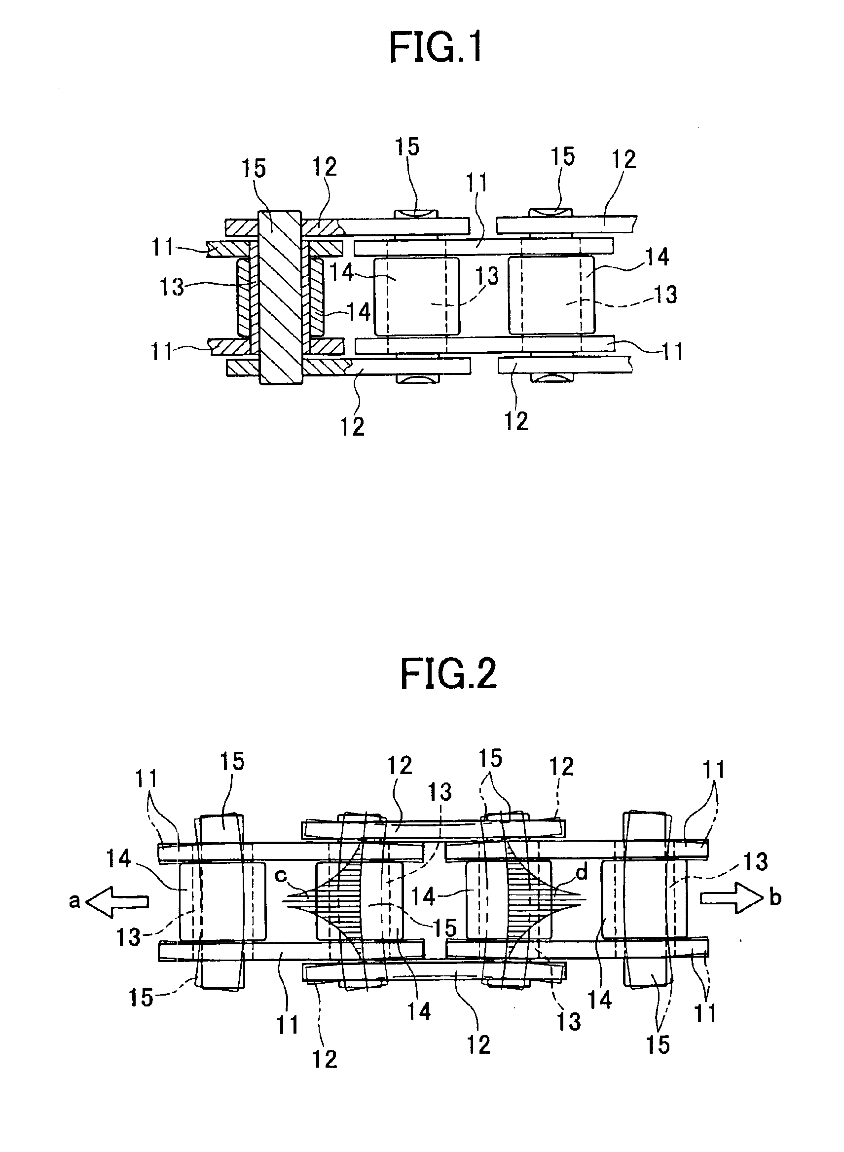
[0027]FIGS. 3 to 8 are drawings related to the first embodiment wherein the present invention is applied to the single-row roller chain for drive transmission shown in FIG. 1.

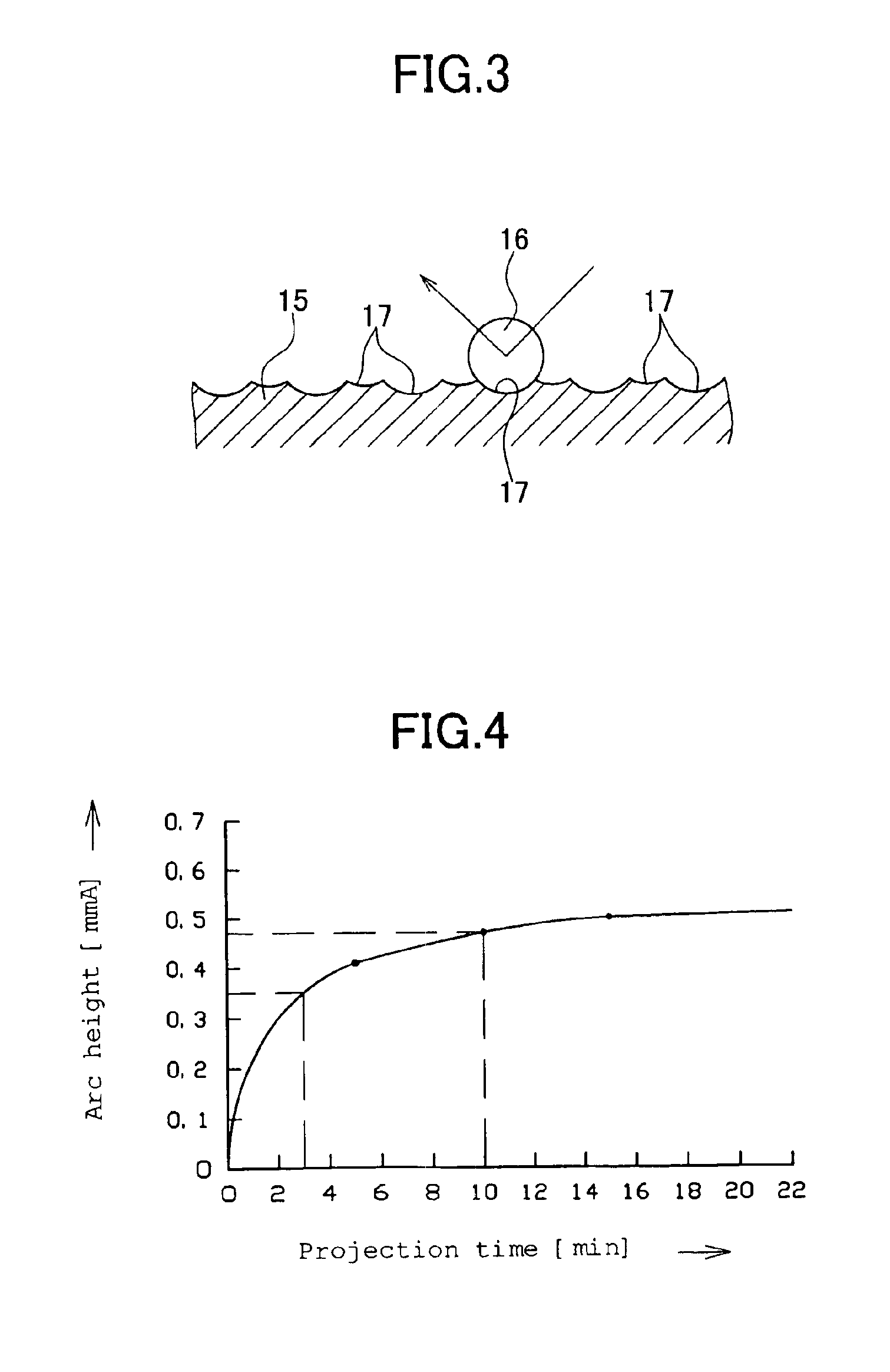
[0028]A chain pin 15, carburized steel or refined steel is used. The chain pin 15 undergoes heat treatment such as quenching, and tempering, and is subsequently subjected to hard shot peening. The hard shot peening is carried out by use of an impeller type shot peening machine (not shown) and a projection member (shot) 16 having hardness higher than that of the pin 15 (refer to FIG. 3). The hard shot peening places a plurality of heat-treated pins 15 in the shot peening machine at random and projects a large number of projection members 16 to the pins 15 by using a rotational centrifugal force of the impeller to form a large number of dimples 17 on the entire surface of the pin 15.

[0029]The dimples 17 are formed by projecting the projection member 16 with high hardness to carburized or refined steel pins 15 to ...

second embodiment

[0043]the present invention will be described with reference to FIG. 9.

[0044]In the second embodiment, secondary shot peening is applied to chain pins 15 following hard shot peening (primary shot peening) shown in the first embodiment. In the secondary shot peening, a large number of projection members 20 are projected to the surface of pins 15 with a value smaller than an arc height values of 0.35 to 0.8 mmA used in the primary shot peening, thereby forming dimples 21 with a size smaller than dimples 17 formed in the primary shot peening. The secondary shot peening uses steel, iron, zinc, bead, or sand balls as the projection member.

[0045]As a result, the surface of pin 15 achieves a hardness higher than that achieved in the first embodiment and reduction in friction resistance between the bushing and the pin, thus resulting in an enhance in durability of the chain. In addition, the dimple 21 can serve as a reservoir for lubricating oil like the dimple 17 in the first embodiment to...

third embodiment

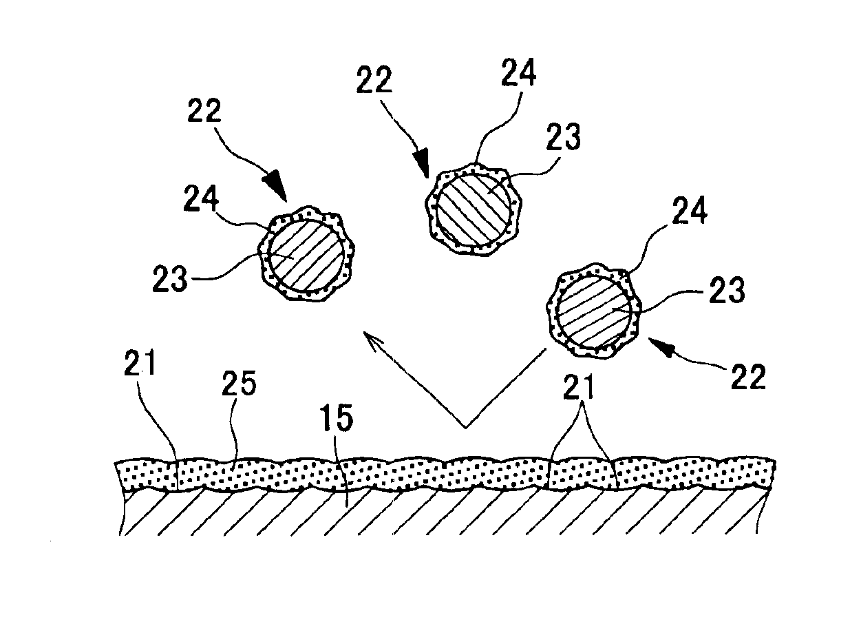
[0046]A third embodiment according to the present invention will be described with reference to FIG. 10. In this embodiment, like the second embodiment, the secondary shot peening is applied to the chain pins 15 following the primary shot peening.

[0047]A large number of steel balls 23, the surface of which is deposited with iron-zinc alloy 24, are used as the projection member 22 for the secondary shot peening in this embodiment and projected to the surface of the pins 15 at an arc height value smaller than 0.35 to 0.8 mmA for the primary shot peening, thereby transforming the dimple 17 which has been formed in the primary shot peening into a smaller-sized dimple 21. Iron-zinc alloy is simultaneously adhered from the surface of the projection member 22 onto the surface of the dimple 21 to form a coating film layer 25.

[0048]As a result, the surface of the pins 15 is rendered as smooth as possible by iron-zinc alloy coating film layer 25 and achieves an improvement in hardness, reduct...


PUM

PropertyMeasurementUnit
diameteraaaaaaaaaa
speedaaaaaaaaaa
speedaaaaaaaaaa

Abstract

A chain including chain pins 15, which connect an inner link plate and an outer link plate, are made of carburized or refined steel, and have the entire surface on which a large number of dimples 17 are provided which are formed through a primary shot peening performed at an arc height value of 0.35 to 0.8 mmA. Furthermore, dimples 21 with a size smaller than that of the dimples 17 are formed by applying a secondary shot peening performed at an arc height value smaller than that of a primary shot peening to the dimples 17 which have been subjected to the primary shot peening.

Description

TECHNICAL FIELD[0001]The present invention relates to chains such as a roller chain, a bushing chain, a leaf chain and a conveyer chain and, more particularly, to a chain pin which connects an inner link plate and an outer link plate.BACKGROUND ART[0002]Various types of chains including a roller chain generally employ steel for components such as inner link plates, outer link plates, and chain pins. With such steel chain, when components thereof reach durability limits due to repeated uses for an extended period of time, fatigue first occurs in the inner and outer link plates so that flexure deformation of the chain pin has a significant effect on fatigue fracture of the inner and outer plates.[0003]FIG. 1 is a plan view of the main portion of a single-row roller chain for drive transmission. The roller chain includes a pair of parallel inner link plates 11, 11, a pair of parallel outer link plates 12, 12 which are disposed at a position outside of and displaced by one pitch from th...

Claims


Application Information

Patent Timeline
Patent Type & Authority Patents(United States)
IPC IPC(8): F16G13/00F16G13/06
CPCF16G13/06Y10T428/12958Y10T428/12451Y10T29/479Y10T428/12993Y10T428/12972
Inventor SUGIYAMA, SHINICHIRO
Owner SUGIYAMA CHAIN
Why Eureka
Try Eureka