Optical proximity correction method utilizing ruled ladder bars as sub-resolution assist features

Inactive Publication Date: 2005-04-19
ASML NETHERLANDS BV
26 Cites 116 Cited by

AI-Extracted Technical Summary

Problems solved by technology

These rules are set by processing and design limitations.
As the size of an integrated circuit is reduced and its density increases, however, the CD of its corresponding mask pattern approaches the resolution limit of the optical exposure tool.
However, as imaging systems move to smaller wavelengths and higher numerical apertures, the ability to manufacture the photomasks with sub-resolution scattering bars sufficiently small becomes a critical issue and a serious problem.
Some of the problems arising with the use of scatter bars are due to the fact that the ability to include scatter bars in a design is limited, for example, by the space dimension between adjacent main features.
However, such placement presents a problem for dense features because the scatter bar cannot be made small enough to avoid printing.
Furthermore,...

Benefits of technology

[0020]Accordingly, it is an object of the present invention to provide a method of forming a photolithography mask having OPC assist features which allows for improved design flexibility and, in particular, improved control over the amo...

Abstract

A photolithography mask for optically transferring a pattern formed in said mask onto a substrate and for negating optical proximity effects. The mask includes a plurality of resolvable features to be printed on the substrate, where each of the plurality of resolvable features has a longitudinal axis extending in a first direction; and a pair of non-resolvable optical proximity correction features disposed between two of the plurality of resolvable features, where the pair of non-resolvable optical proximity correction features has a longitudinal axis extending in a second direction, wherein the first direction of the longitudinal axis of the plurality of resolvable features is orthogonal to the second direction of the longitudinal axis of the pair of non-resolvable optical proximity correction features.

Application Domain

Technology Topic

Optical proximity correctionEngineering

Image

  • Optical proximity correction method utilizing ruled ladder bars as sub-resolution assist features
  • Optical proximity correction method utilizing ruled ladder bars as sub-resolution assist features
  • Optical proximity correction method utilizing ruled ladder bars as sub-resolution assist features

Examples

  • Experimental program(2)

Example

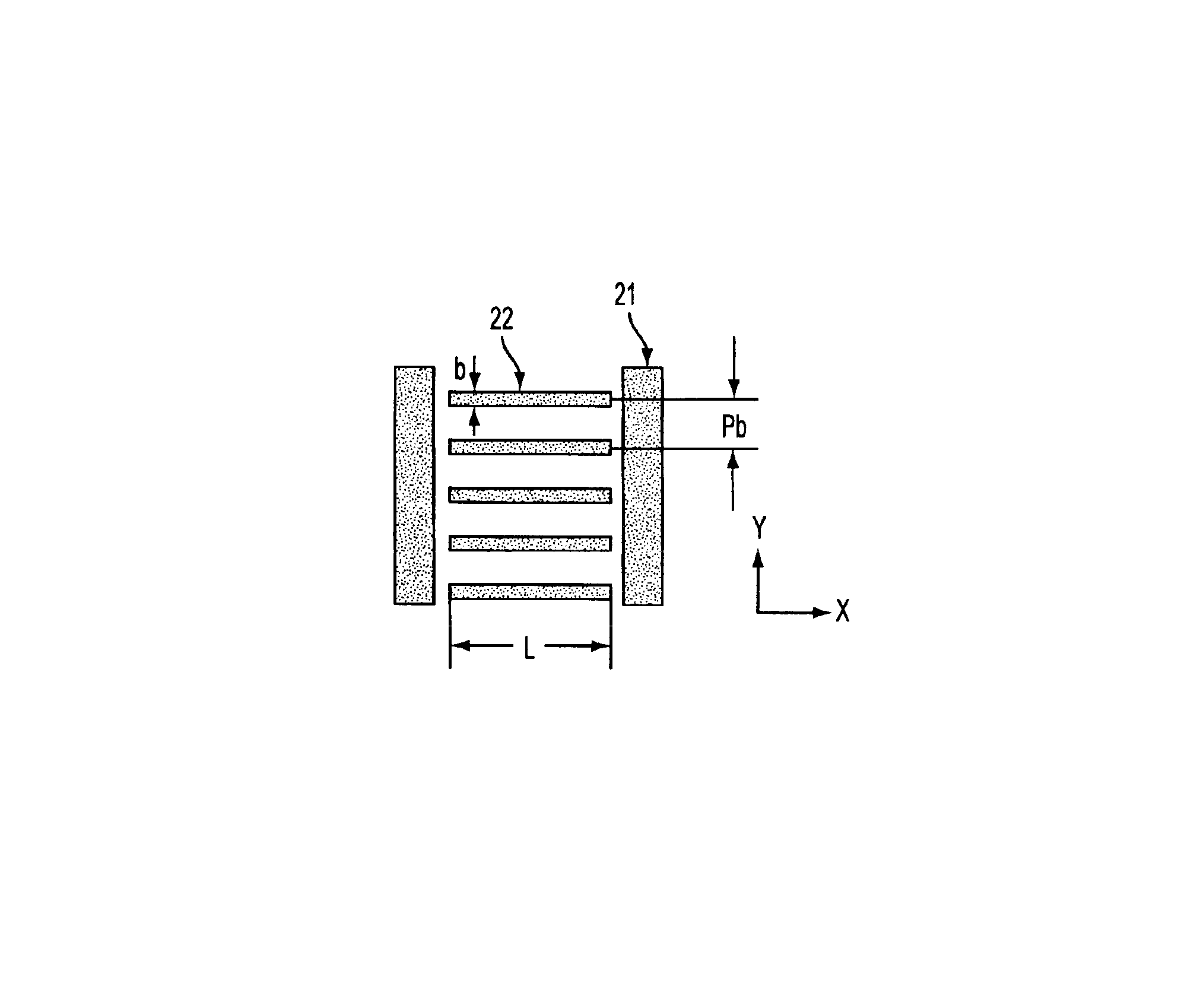
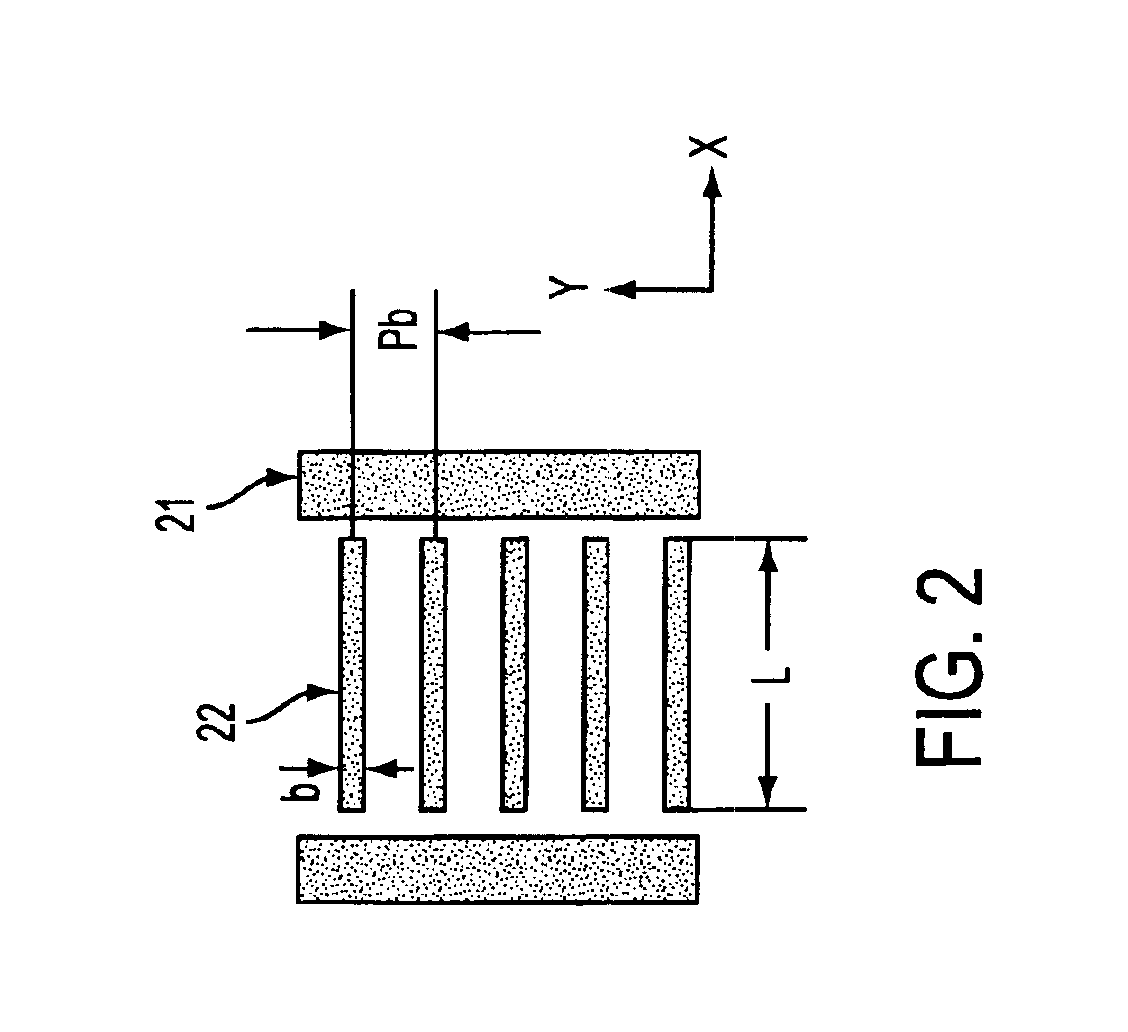
[0042]FIG. 2 illustrates an exemplary mask utilizing a first embodiment of the ladder bar assist features (also referred to as ladder bars) of the present invention. Referring to FIG. 2, a plurality of ladder bar assist features 22 are placed between main features 21. Importantly, each of the ladder bar assist features 22 is positioned such that the longitudinal axis of the ladder bar assist feature 22 extends perpendicularly to the longitudinal axis of the main features 21. As shown, the ladder bar assist features 22 extend parallel to one another. In addition, the length of the ladder bar assist features of the given embodiment is such that the ladder bars 22 extend substantially the entire length of the space between the edges of the main features 21. In the embodiment illustrated in FIG. 2, the ladder bars 22 do not contact the edges of the main features 21. It is noted, however, that it is also possible for the ladder bars 22 to contact the edges of the main features.
[0043]Further, as with scatter bars, each ladder bar assist feature 22 is sub-resolution such that the ladder bar assist feature does not print. In other words, the size of each ladder bar assist feature (b) taken in consideration with the length of the ladder bar size (taken in the “X” direction) and the ladder bar pitch (pb) must be such that the ladder bar assist features remain sub-resolution. In other words, the bar pitch must be beyond the resolution limits of the imaging tool, or below λ/(σ+1)NA, where λ is the exposure wavelength, σ is the partial coherence factor, and NA is the numerical aperture of the objective lens. The size of the ladder bar in the “Y” direction should remain small enough such that the ladder bar does not print yet large enough so as to result in a reduction in the space intensity as defined by equation (1) It is noted that the optimal settings and/or sizing of the ladder bar assist features for a given mask design can be determined by empirical methods and/or by simulation. It is further noted that ladder bar assist features can be opaque for use with dark line main features, or alternatively, transparent for use with clear space features.
[0044]The presence of the sub-resolution ladder bar assist features provides for the control of the main feature diffraction along the main feature edges, as well as the end of the main features. More specifically, by placing the ladder bar assist features 22 between the edges of the main features, the primary diffraction orders, namely, the zero diffraction order, the first diffraction order and the second diffraction order, can be determined utilizing the following equations:
Mag. zero order=[(pb−b)/pb](s/p)  (2)
Mag. first order=[(pb−b)/pb]|(s/p)sinc(s/p)|  (3)
Mag. second order=[(pb−b)/pb]|(s/p)sinc(2s/p)|  (4)
where s is the space (i.e., width) between main features 21, p is the pitch between main features, pb is the bar pitch (in the “Y” direction), and b is the bar size (in the “Y” direction). It is noted that the foregoing equations relate to the diffraction orders in the “X” direction, and presume that the width of the ladder bars is such that the bars extend across the entire opening in the “X” direction.
[0045]FIG. 5(a) illustrates an aerial image corresponding to an exemplary mask having no OPC assist features, and FIG. 5(b) is an aerial image of the same mask as utilized in FIG. 5(a), but modified to include the ladder bar assist features of the present invention. Specifically, FIG. 5(a) illustrates the results of 150 nm main features having a 1:5 line:space duty ratio (semi-isolated features) being imaged utilizing a 248 nm wavelength (λ), a 0.70 lens pupil NA, and a partial coherence value (σ) of 0.85. The diffraction limited pitch of the illumination system is 192 nm. The images in FIG. 5(a) correspond to best focus (51) and 300 nm of defocus (52). As shown in FIG. 5(a), the resulting isofocal inflection point is approximately 0.8, which is significantly larger than the value of the isofocal inflection point corresponding to mask features having a line:space duty ratio of 1:1 (for a 1:1 duty ratio, the resulting isofocal inflection point is on the order of 0.34). It is noted that the isofocal inflection point corresponds to the location at which the image prints with minimal loss regardless of whether the image is printed with substantially no defocus (i.e., best focus) or with 300 nm of defocus. Variations in the location of the isofocal inflection points associated with the dense and semi-isolated features make it difficult to print these features with a common process window. Accordingly, it is desirable to reduce the isofocal inflection point associated with semi-isolated features so as to improve the process overlap when such dense and semi-isolated features are included on the same mask.
[0046]FIG. 5(b) corresponds to the same mask as utilized to generate the image of FIG. 5(a), with the exception that the ladder bar assist features are added to the mask. The ladder bar assist features utilized have a size of 60 nm (dimension “b” in FIG. 2) and a pitch, pb, of 185 nm. Further, the ladder bar assist features have a length such that the ladder bars extend across the entire space opening between the main features. As stated, as the diffraction limited pitch of the imaging system utilized for illumination is 192 nm, the pitch of the ladder bar assist features is sufficiently below the pitch limitation of the imaging system such that the ladder bar assist features do not print. The foregoing configuration/dimensions of the ladder bar assist features result in the collection of only the zero diffraction order term due to the frequency of the ladder bar assist features. As such, utilizing equation (1) above, the resulting intensity reduction between the main features is (0.676)2 or 46%.
[0047]It is noted that one of the significant advantages of the ladder bar assist features is that they allow for the intensity reduction value to be easily and significantly varied (for example, above and below the 46% value obtained in the present example) in order to optimize imaging performance by simply varying the size of the ladder bars and the pitch of the ladder bars. This is possible, in part, because due to the orientation of the ladder bars relative to the main feature, the pitch and size of the ladder bars are no longer constrained by the space between the main features. It is the length of the main feature (the “Y” direction in FIG. 2) that defines the number of ladder bars that can be included as OPC features. In contrast, the number of scatter bars that can be included between main features is limited by the space between the features, for conventional OPC and as a practical matter, it is becoming increasingly difficult to accommodate multiple scatter bars between main features while maintaining the scatter bars sub-resolution.
[0048]Returning again to FIG. 5(b), as shown, the use of the foregoing ladder bar assist features advantageously results in the reduction of the isofocal inflection point for the features having a line:space duty ratio of 1:5 to a value below 0.4, which is significantly closer to the isofocal inflection point of features having a 1:1 line: space duty ratio. As a result of the reduction of the location of the isofocal inflection point for the features having a line:space duty ratio of 1:5, it is possible to print these semi-isolated features and dense features with a common process window.
[0049]As mentioned above, it is also possible to utilize the ladder bar assist features of the present invention to control or correct optical proximity effects at the ends of the main features. This can be accomplished by controlling where the ladder bar assist feature is positioned relative to the end of the main features. FIG. 4 illustrates an exemplary mask utilizing the ladder bar assist features to compensate for line end shortening. As shown in FIG. 4, the ladder bar assist features 42 extend beyond the ends of the main features 41 so as to prevent the occurrence of line end shortening.

Example

[0050]In accordance with a second embodiment of the present invention, the length of the ladder bar assist features disposed between the main features are variable. As explained in further detail below, by varying the length of the ladder bar assist features it is possible to introduce a frequency component associated with the ladder bar assist features that provides for additional image control.
[0051]FIG. 3 illustrates an exemplary mask utilizing the second embodiment of the ladder bar assist features of the present invention. As shown in FIG. 3, the ladder bar assist features 32 do not extend across the entire space between the main features 31, and the length of each of the ladder bar assist features is equal. As a result, the ladder bar assist features can be considered a group 33, which possesses a unique size and frequency when the group is repeatedly disposed between main features 31. FIG. 3 illustrates a single group 33 disposed between two main features 31. It is noted that the length of the ladder bar assist features determines the width of group 33.
[0052]By controlling the width of the group 33 it is possible to introduce a frequency component associated with the groups 33, which is preferably a harmonic of the frequency of the main features, that advantageously functions to reduce the zero order diffraction component, without a corresponding reduction in the first and second order diffraction components. As such, this additional frequency component allows for improved image control. In comparison, in the first embodiment of the present invention, in which the ladder bar assist features are disposed across substantially the entire space between the main features, no such frequency component is introduced along the main feature direction. Accordingly, in the first embodiment, a reduction of all diffraction orders occurs, as shown by equations (2), (3) and (4).
[0053]The effect that the width of the ladder bar groups has on the magnitude of the zero, first and second order diffraction components is calculated for the exemplary mask illustrated in FIG. 6. Referring to FIG. 6, the mask electric field 60 is illustrated for main features 61 and the groups 62 of ladder bar assist features, one of which is disposed between each pair of main features 61. As stated, by introducing a ladder bar assist feature group 62 within the space between the mask features 61, the primary diffraction orders for the mask field are modified. Specifically, for opaque main features with clear openings, the magnitude of the primary diffraction orders become:
[0054] (5) Mag. zero order = [1-(g/s)(1-Ig)](s/p) (6) Mag. first order = |(s/p)sinc(s/p)-(1-Ig)(g/p)sinc(g/p)| (7) Mag. second order = |(s/p)sinc(2s/p)-(1-Ig)(g/p)sinc(2g/p)|
where s is the main feature space width, p is the main feature pitch, g is the width of the ladder bar assist feature grouping, and Ig is the resulting group intensity of the ladder bar assist feature group, which can be calculated utilizing equation (1) above.
[0055]As can be seen from the foregoing equations, the modulation of the primary diffraction orders is unique and a function of the parameters of the grouped ladder bar assist features. FIGS. 7(a)-(c) illustrate how the primary diffraction orders are influenced by the grouped ladder bar assist features. Zero order magnitude values are plotted along with the first and second order magnitude values normalized to the resulting value of the zero order. The images illustrated in FIGS. 7(a)-(c) correspond to a mask comprising features having a 1:2.5 line:space duty ratio, with grouped ladder bar assist features having a width ranging from zero to substantially the entire space between the main features. A fractional width of zero implies no group ladder bar assist features are present and a width of 1 implies that ladder bar assist features occupy substantially the full space between the main features (as in the first embodiment of the present invention). In addition, in the given embodiment, the transmission value of the groups of ladder bar assist features are allowed to vary between 0% and 100% (i.e., no assist feature).
[0056]Referring to FIGS. 7(a)-7(c), it can be seen that for the case where the width of the ladder bar assist features occupy substantially the entire space between the main features as in the first embodiment (i.e., the right side of the plots in FIGS. 7(a)-7(c)), the normalized first and second order diffraction values remain the same. The left side of the plots of FIGS. 7(a)-7(c) correspond to the scatter bar solution, with zero transmission values and small fractional widths. It is noted that problems arise with scatter bar techniques as the size of the scatter bar increases and the magnitude of the second order diffraction component increases to the point where the scatter bar prints. It has been shown that a 0.3 width scatter bar will print in resist. A practical limit regarding the width of scatter bars is on the order of 0.15-0.2 fractional width. However, in contrast to scatter bars, as shown in FIG. 7(c), by adjusting the width of the grouped ladder bar assist features, the printability issues resulting from large second order effects can be reduced, thus making the use of the ladder bar assist features a viable solution. More specifically, as shown in FIG. 7(c), by properly selecting the width of the groups of ladder bar assist features 62, it is possible to minimize the increase in the magnitude of the second diffraction order component thereby reducing the likelihood that the ladder bar assist features will print.
[0057]FIG. 8 is an aerial image illustrating the effect of a grouped ladder bar assist feature. The image illustrated corresponds to a mask comprising 150 nm features having a 1:5 line:space duty ratio, with grouped ladder bar assist features having a group width equal to ⅔ of the space width between the main features or 500 nm. Similar to the previous example, the pitch of the ladder bar assist features is 185 nm, which is sufficiently below the pitch limitation of the imaging system (i.e., the ladder bar assist features are sub-resolution), and the width size of the bar is 60 nm. The images of FIG. 8 correspond to an image taken at best focus 81 and an image taken at 300 nm of defocus 82. The configuration of the mask utilized to generate the images of FIG. 8 results in the collection of only the zero diffraction order of the ladder bar assist features within the group since their pitch is below the diffraction limits of resolution, resulting in an intensity reduction between the main features of (0.78)2 or 0.61 or 61%. The foregoing is calculated utilizing equation (8) below:
Space Reduction Intensity=[((pb−b)/pb)(g/s)+(s−g)/s]2=0.61  (8)
where pb is the ladder bar pitch, b is the width of the ladder bar, s is the main feature space width, and g is the width of the ladder bar assist feature grouping. It is noted that one of the important aspects of the invention is that this transmission reduction value can be readily varied, either higher or lower, by adjusting the width of the group of the ladder bar assist features, or by adjusting the pitch and size of the ladder bar assist features.
[0058]When compared to the image set forth in FIG. 5(b), the results of the image set forth in FIG. 8 makes clear the significant improvement obtained by the utilizing the grouped ladder bar assist features having a variable width. More specifically, the image contrast for the best focused images in FIG. 5(b) is 0.37, while the image contrast for the image in FIG. 8 is 0.68,
Image Contrast=(Imin−Imax)/(Imin+Imax)  (9)
where Imin and Imax are the minimum and maximum intensities. It is noted that although the isofocal inflection point of the full space width ladder bar assist features of FIG. 5(b) is 0.78 and is lower than the value of the grouped ladder bar assist features of FIG. 8, which is 0.44, this is offset by the loss in image contrast. Importantly, by utilizing the grouped ladder bar assist features having varying width, it is possible to control this tradeoff, where a wider group can result in a lower isofocal intensity and a narrower group can result in larger contrast.
[0059]FIG. 9 illustrates an exemplary mask layout utilizing the ladder bar OPC assist features of the present invention. The mask layout illustrated in FIG. 9 represents a two dimensional application of mainline features 91, having groups of ladder bar assist features 92 disposed between the main line features 91. In addition, the exemplary mask also illustrates the use of prior art scatter bars 93. The use of such OPC correction features can provide significant improvement regarding process overlap across a variety of feature sizes and pitch values.
[0060]As noted above, the present invention provides significant advantages over known OPC assist features. For example, one of the significant advantages of the ladder bar assist features of the present invention is that they allow for the intensity reduction value to be easily and significantly varied in order to optimize imaging performance by simply varying the size of the ladder bars and the pitch of the ladder bars. This is possible, in part, because due to tile orientation of the ladder bars relative to the main feature, the pitch and size of the ladder bars are no longer constrained by the space between the main features. In addition, by properly selecting the width of the groups of ladder bar assist features, it is possible to minimize the increase in the magnitude of the second diffraction order component, thereby reducing the likelihood that the ladder bar assist feature will print.
[0061]It is further noted that numerous variations of the present invention are also possible. For example, the ladder bar assist features can be utilized with off-axis illumination techniques, such as quadrapole illumination. In addition, as noted above it is also possible to vary the transmission % of the ladder bar assist features so as to allow further optimization of the resulting image.
[0062]FIG. 10 schematically depicts a lithographic projection apparatus suitable for use with a mask designed with the aid of the current invention. The apparatus comprises: [0063] a radiation system Ex, IL, for supplying a projection beam PB of radiation. In this particular case, the radiation system also comprises a radiation source LA; [0064] a first object table (mask table) MT provided with a mask holder for holding a mask MA (e.g. a reticle), and connected to first positioning means for accurately positioning the mask with respect to item PL; [0065] a second object table (substrate table) WT provided with a substrate holder for holding a substrate W (e.g. a resist-coated silicon wafer), and connected to second positioning means for accurately positioning the substrate with respect to item PL; [0066] a projection system (“lens”) PL (e.g. a refractive, catoptric or catadioptric optical system) for imaging an irradiated portion of the mask MA onto a target portion C (e g. comprising one or more dies) of the substrate W.
[0067]As depicted herein, the apparatus is of a transmissive type (i.e. has a transmissive mask). However, in general, it may also be of a reflective type, for example (with a reflective mask). Alternatively, the apparatus may employ another kind of patterning means as an alternative to the use of a mask; examples include a programmable mirror array or LCD matrix.
[0068]The source LA (e.g. a mercury lamp or excimer laser) produces a beam of radiation. This beam is fed into an illumination system (illuminator) IL, either directly or after having traversed conditioning means, such as a beam expander Ex, for example. The illuminator IL may comprise adjusting means AM for setting the outer and/or inner radial extent (commonly referred to as σ-outer and σ-inner, respectively) of the intensity distribution in the beam. In addition, it will generally comprise various other components, such as an integrator IN and a condenser CO. In this way, the beam PB impinging on the mask MA has a desired uniformity and intensity distribution in its cross-section.
[0069]It should be noted with regard to FIG. 10 that the source LA may be within the housing of the lithographic projection apparatus (as is often the case when the source LA is a mercury lamp, for example), but that it may also be remote from the lithographic projection apparatus, the radiation beam that it produces being led into the apparatus (e.g. with the aid of suitable directing mirrors); this latter scenario is often the case when the source LA is an excimer laser (e.g. based on KrF, ArF or F2 lasing). The current invention encompasses both of these scenarios.
[0070]The beam PB subsequently intercepts the mask MA, which is held on a mask table MT. Having traversed the mask MA, the beam PB passes through the lens PL, which focuses the beam PB onto a target portion C of the substrate W. With the aid of the second positioning means (and interferometric measuring means IF). the substrate table WT can be moved accurately, e.g. so as to position different target portions C in the path of the beam PB. Similarly, the first positioning means can be used to accurately position the mask MA with respect to the path of the beam PB, e.g. after mechanical retrieval of the mask MA from a mask library, or during a scan. In general, movement of the object tables MT, WT will be realized with the aid of a long-stroke module (coarse positioning) and a short-stroke module (fine positioning), which are not explicitly depicted in FIG. 10. However, in the case of a wafer stepper (as opposed to a step-and-scan tool) the mask table MT may just be connected to a short stroke actuator, or may be fixed.
[0071]The depicted tool can be used in two different modes: [0072] In step mode, the mask table MT is kept essentially stationary, and an entire mask image is projected in one go (i.e. a single “flash”) onto a target portion C. The substrate table WT is then shifted in the x and/or y directions so that a different target portion C can be irradiated by the beam PB; [0073] In scan mode, essentially the same scenario applies, except that a given target portion C is not exposed in a single “flash”. Instead, the mask table MT is movable in a given direction (the so-called “scan direction”, e.g. the y direction) with a speed ν, so that the projection beam PB is caused to scan over a mask image; concurrently, the substrate table WT is simultaneously moved in the same or opposite direction at a speed V=Mν, in which M is the magnification of the lens PL (typically, M=¼ or ⅕). In this manner, a relatively large target portion C can be exposed, without having to compromise on resolution.
[0074]Although certain specific embodiments of the present invention have been disclosed, it is noted that the present invention may be embodied in other forms without departing from the spirit or essential characteristics thereof. The present embodiments are therefore to be considered in all respects as illustrative and not restrictive, the scope of the invention being indicated by the appended claims, and all changes that come within the meaning and range of equivalency of the claims are therefore intended to be embraced therein.

PUM

no PUM

Description & Claims & Application Information

We can also present the details of the Description, Claims and Application information to help users get a comprehensive understanding of the technical details of the patent, such as background art, summary of invention, brief description of drawings, description of embodiments, and other original content. On the other hand, users can also determine the specific scope of protection of the technology through the list of claims; as well as understand the changes in the life cycle of the technology with the presentation of the patent timeline. Login to view more.

Similar technology patents

Environment-friendly modified benzoxazine resin and preparation method thereof

ActiveCN113817117AImprove design flexibilityImprove controllabilityPhosphazeneThermal reaction
Owner:北京玻钢院复合材料有限公司

Classification and recommendation of technical efficacy words

  • Improve control
  • Improve design flexibility

Control method for downhole steering tool

ActiveUS20050269082A1Reduce tortuosityImprove controlSurveyDirectional drillingCommunication bandwidthEnvironmental geology
Owner:SCHLUMBERGER TECH CORP

Disk drive suspension

ActiveUS20140022671A1Improve design flexibilityArm with actuatorsRecord information storageMicroactuatorMechanical engineering
Owner:NHK SPRING CO LTD

Shaft-driven motorcycle with pivotally mounted swing arm and related support structure

ActiveUS20090057046A1Increase ground clearanceImprove design flexibilityRotary transmissionsCrankshaft transmissionEngineeringDrive shaft
Owner:HONDA MOTOR CO LTD

Airbag device

Owner:ASHIMORI INDS
Why Eureka
Try Eureka