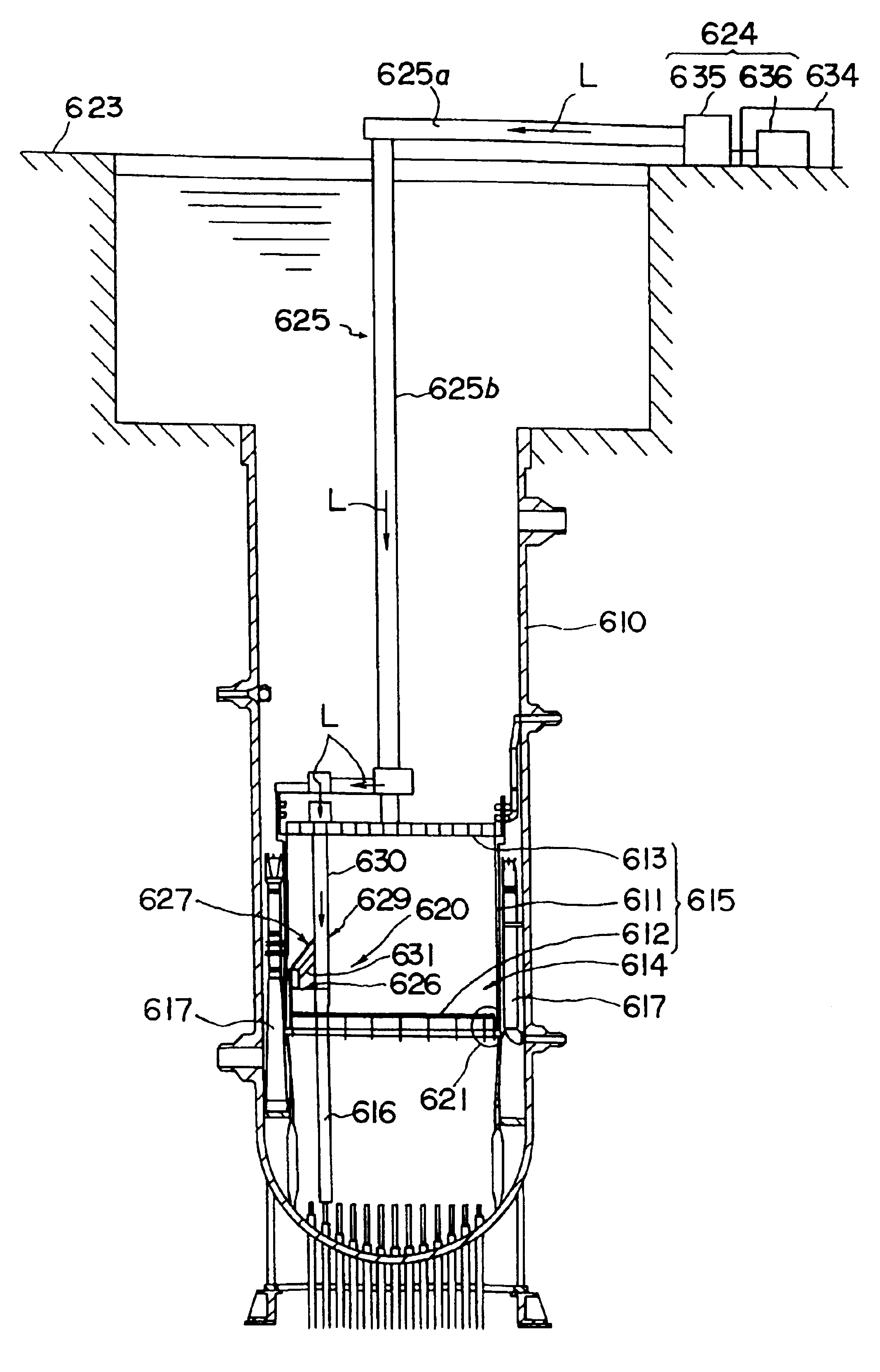
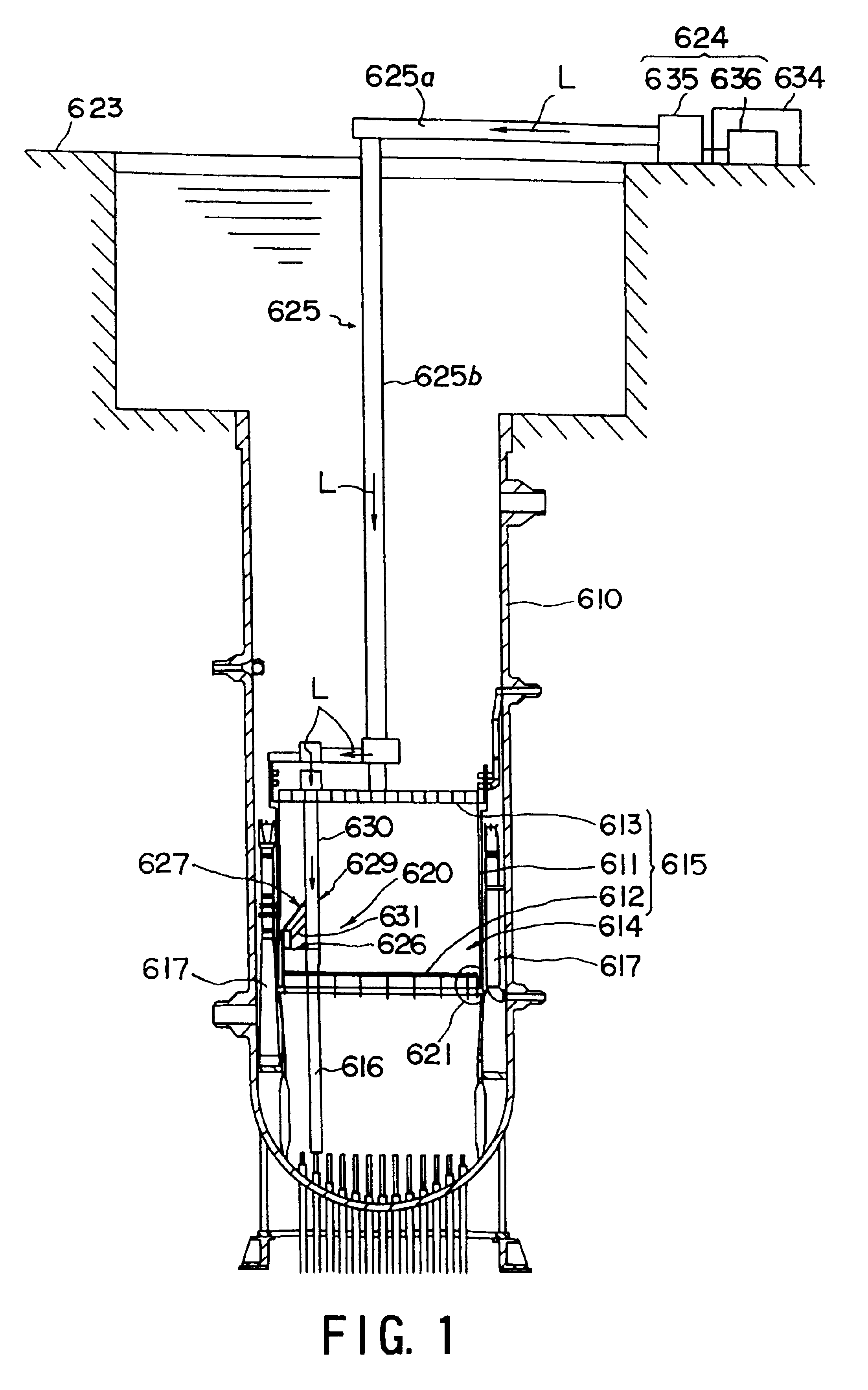
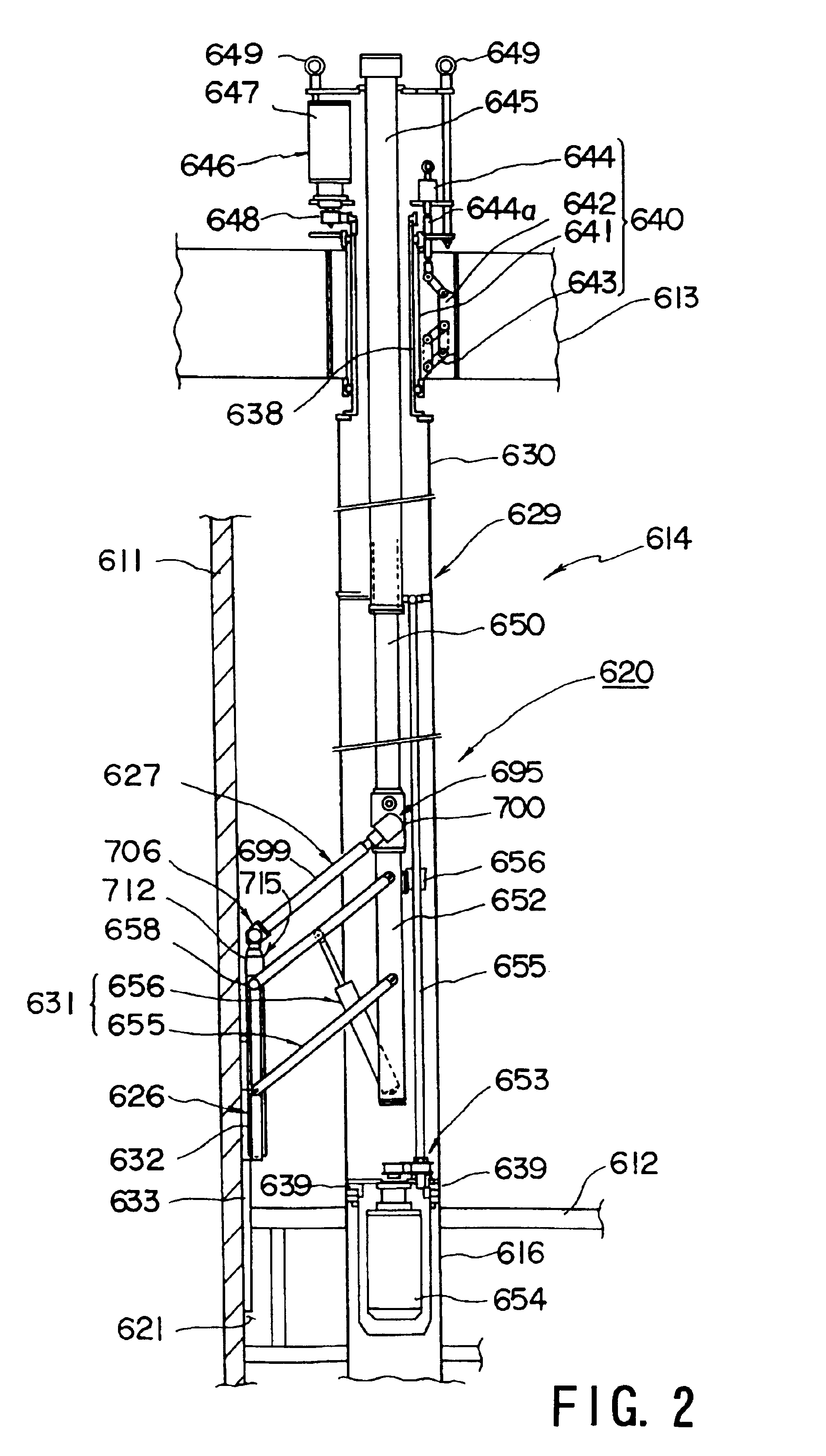
Laser emission head, laser beam transmission device, laser beam transmission device adjustment method and preventive maintenance/repair device of structure in nuclear reactor

a technology of laser beam transmission and laser beam, which is applied in the direction of metal-working equipment, welding equipment, manufacturing tools, etc., can solve the problems of deterioration, power or energy for introducing laser beams in optical fibers, and members among incore structures that cannot be easily changed, so as to prevent deterioration in working efficiency

Inactive Publication Date: 2005-04-19
KK TOSHIBA
View PDF15 Cites 46 Cited by
  • Summary
  • Abstract
  • Description
  • Claims
  • Application Information

AI Technical Summary

Benefits of technology

[0087]Only the laser oscillator can be recovered to the outside of the retro-reflector such that the turning vehicle is left in the reactor. If adjustment must be performed during the operation because, for example, maintenance of the laser oscillator is required, only the laser oscillator can easily be moved upwards to the operation floor to perform direct maintenance. Therefore, deterioration in the working efficiency can be prevented.

Problems solved by technology

There is apprehension that members among the incore structures, which cannot easily be changed, deteriorate because the members are subjected to a severe environment as a result of the operation of the nuclear power plant for a long time and influences of irradiation of neutrons.
In particular, portions adjacent to welded portions in the incore structure have potential probability of stress corrosion cracking because of sensitization of the materials caused by heat inputs during the welding operations and influences of tensile residual stress.
When the optical fiber is employed, the power or the energy for introducing the laser beam in the optical fiber has a limitation.
However, a difficulty is imposed when a vertical welding line (a welding line on the inside of V5) in the lower half of the intermediate body of the shroud or a horizontal welding line (a welding line on the inside of H6a) at the lower end of the inner portion of an intermediate body of the shroud is welded.
However, the laser emitting head 608 cannot transmit a laser beam to the above-mentioned small cylindrical portion.
The foregoing method encounters undesirably reduction in the incidental angle, causing a problem to arise in that a sufficiently high energy density required to perform the machining operation cannot be realized.
There arises another problem in that a precise locating mechanism must be provided to scan the points which must be irradiated because the distance which must be irradiated is elongated excessively.
As a result, there arises a problem that the preventive-maintenance / repair apparatus becomes too complicated and, therefore, the reliability deteriorates.
When the above-mentioned light transmission apparatus is used to perform a preventive maintenance operation or a repair operation in a nuclear power plant, there arise the following problems in an operation for transmitting and applying laser beams to an incore structure of a nuclear reactor.
Since a sufficiently large working space cannot be permitted in the nuclear reactor and the incore structures are disposed in the core, the light transmission apparatus has a complicated transmission passage.
As a result, errors are frequently made during the transmission, a large number of places must be supervised and a large number of the optical supervising units, such as CCD cameras, must be provided.
If the environment is changed during transmission of the laser beam in the light transmission apparatus, there is apprehension that the optical axis of the light transmission passage is misaligned owning to the change in the environment.
As a result, the laser beam is undesirably swayed and, therefore, there arises a problem in that the laser beam cannot stably be transmitted to a required transmission point.
If a large number of CCD cameras are provided for the light transmission apparatus, a long time is required to adjust the CCD cameras.
Moreover, the electronic elements, such as the CCD camera, cannot be used in an environment in which the high intensity of radioactive rays is shown.
However, the foregoing apparatus cannot be operated to machine the outside of the shroud body, that is, the outer wall of the shroud body, the inner surface of the pressure chamber and a space called an annulus portion in the form of a small cylindrical shape interposed between baffle plates and having a multiplicity of jet pumps stood erect therebetween.
Moreover, no specific mechanism and structure has been disclosed which can efficiently be moved from the core in any one of all 360° horizontal directions.

Method used


Image

  • Laser emission head, laser beam transmission device, laser beam transmission device adjustment method and preventive maintenance/repair device of structure in nuclear reactor
  • Laser emission head, laser beam transmission device, laser beam transmission device adjustment method and preventive maintenance/repair device of structure in nuclear reactor
  • Laser emission head, laser beam transmission device, laser beam transmission device adjustment method and preventive maintenance/repair device of structure in nuclear reactor

Examples


first embodiment

[0199]FIG. 9 is a basic structural view showing the light transmission apparatus according to the present invention.

[0200]Referring to FIG. 9, reference numeral 810 represents a light transmission apparatus for transmitting laser beams in the air. The light transmission apparatus 810 comprises a light transmission means 812 serving as a laser beam transmission means formed by combining mirrors to constitute a light transmission passage 811; a main laser emitting unit 813 serving as a light source for emitting laser beams for machining, inspection or preventive-maintenance / repair to the light transmission passage 811; and a guide laser emitting unit 814 for emitting guide laser beams which are guide laser beams for adjusting the optical axis of the light transmission passage 811.

[0201]The laser beam emitted from the main laser emitting unit 813 passes through a dichroic mirror 815 which is a light synthesizing means so as to be introduced into the light transmission passage 811. The ...

second embodiment

[0273]FIG. 10 is a basic diagram showing the light transmission apparatus according to the present invention.

[0274]The light transmission apparatus 870 according to the second embodiment is basically different from the light transmission apparatus 870 according to the first embodiment in a plurality of guide laser units 871 and 872 for emitting laser beams having different wavelengths. Since the plurality of the guide laser units 871 and 872 are provided, the polarizing optical means is not required. Therefore, a sampling detection passage 873 has a different structure. The other structures are substantially the same as those of the light transmission apparatus 810 according to the first embodiment. Therefore, the same reference numerals are given to simplify description.

[0275]FIG. 10 shows an example having two guide laser units 871 and 872. The first guide laser unit 871 is a He—Ne laser unit for emitting He—Ne laser beams, while the second guide laser unit 872 is a He—Cd laser un...


PUM

PropertyMeasurementUnit
depthaaaaaaaaaa
widthaaaaaaaaaa
angleaaaaaaaaaa

Abstract

A laser emitting head for irradiating a portion to be machined with laser beams outputted from a laser unit (624) incorporates an emitting head body having a light guide member (625) in the head for guiding the laser beams; a light converging lens (677) for converging the laser beams transmitted from the light guide member in the head; a reflecting mirror (678) for irradiating the portion to be machined with the converged laser beams; mirror rotating means (684) for holding the reflecting mirror to be rotative around the optical axis of the laser beam; distance-adjustment means (674) for adjusting the relative distance between the reflecting mirror and the converging lens; and moving means (665) for moving the reflecting mirror and the converging lens such that the relative distance is maintained so that the light guide member in the head. The converging lens and the reflecting mirror can be introduced/discharged with respect to a portion to be machined and formed in a narrow gap in an incore structure. As a result, a preventive-maintenance/repair operation using laser beams and arranged to be performed in a narrow gap in the incore structure can safely and efficiently be performed.

Description

FIELD OF THE INVENTION[0001]The present invention relates to a light transmission technique for transmitting light in a light transmission passage formed by combining mirrors with one another. More particularly, the present invention relates to a light transmission apparatus which is capable of automatically and stably adjusting the optical axis of an optical passage when light is accurately transmitted to the position of a target which must be irradiated with light and which is located in, for example, a nuclear power plant, to an adjusting method therefor and to an incore-structure preventive-maintenance / repair apparatus which is capable of stably and efficiently performing preventive-maintenance / repair of an incore structure.BACKGROUND ART[0002]Hitherto, incore structures of a light water reactor, for example, a boiling water reactor, have been made of materials having sufficient corrosion resistance in high temperature and high pressure environment in water and having satisfacto...

Claims


Application Information

Patent Timeline
Patent Type & Authority Patents(United States)
IPC IPC(8): B23K26/10
CPCB23K26/106B23K26/0069B23K26/356
Inventor SATO, KATSUHIKOKIMURA, MOTOHIKOSANO, YUJISHIMAMURA, MITSUAKIIGAKURA, HIROAKIOCHIAI, MAKOTOMUKAI, NARUHIKOYODA, MASAKITOGASAWA, YUTAKAKITAJIMA, YASUMIITO, TOMOYUKIUEHARA, TAKUYAKONDO, MAKOTOSATO, YOSHIFUMI
Owner KK TOSHIBA
Why Eureka
Try Eureka