High accuracy inertial sensors from inexpensive components

a technology of inertial sensors and components, applied in the field of gyroscopic instruments, can solve the problems of low-grade performance of state-of-the-art mems devices and cannot compete with established sensors in such high-accuracy application areas, and achieve the effects of a wider range of applications, a potentially better collective performance, and a wide range of applications

Inactive Publication Date: 2005-04-19
CALIFORNIA INST OF TECH
View PDF8 Cites 42 Cited by
  • Summary
  • Abstract
  • Description
  • Claims
  • Application Information

AI Technical Summary

Benefits of technology

[0009]The invention is a systematic method to combine multiple gyro devices so that the collective performance is potentially better than that of any single device. In practice, the measurements from many inexpensive MEMS devices on a single chip can be analytically combined in a real-time processing filter to raise their performance from low-grade to high grade, and command a much wider range of applications.
[0010]The basic prior art approach of Allan was to study the behavior of the three sports watches relative to coordinated universal time (UTC) time, and relative to each other. This formed a basis for combining them into an improved time estimate. The present approach is different in at least two important ways. First, gyro rate measurements are combined rather than time measurements. Second, a minimum-variance estimation approach and Kalman filtering are used to provide a systematic theory and implementation for combining devices. The Kalman filtering approach has the advantage of being a systematic method to ensure a minimum variance rate estimate.
[0011]The invention utilizes the collective behavior of multiple MEMS devices to offset deficiencies occurring at the single-device level, thereby improving overall performance to the point where they can be considered as a competitive technology for future NASA/JPL missions, aircraft, land vehicles and underwater

Problems solved by technology

Unfortunately, present state-of-the-art MEMS devices have low-grade performance and cannot compete with established sensors in such high-accurac

Method used


Image

  • High accuracy inertial sensors from inexpensive components
  • High accuracy inertial sensors from inexpensive components
  • High accuracy inertial sensors from inexpensive components

Examples


examples

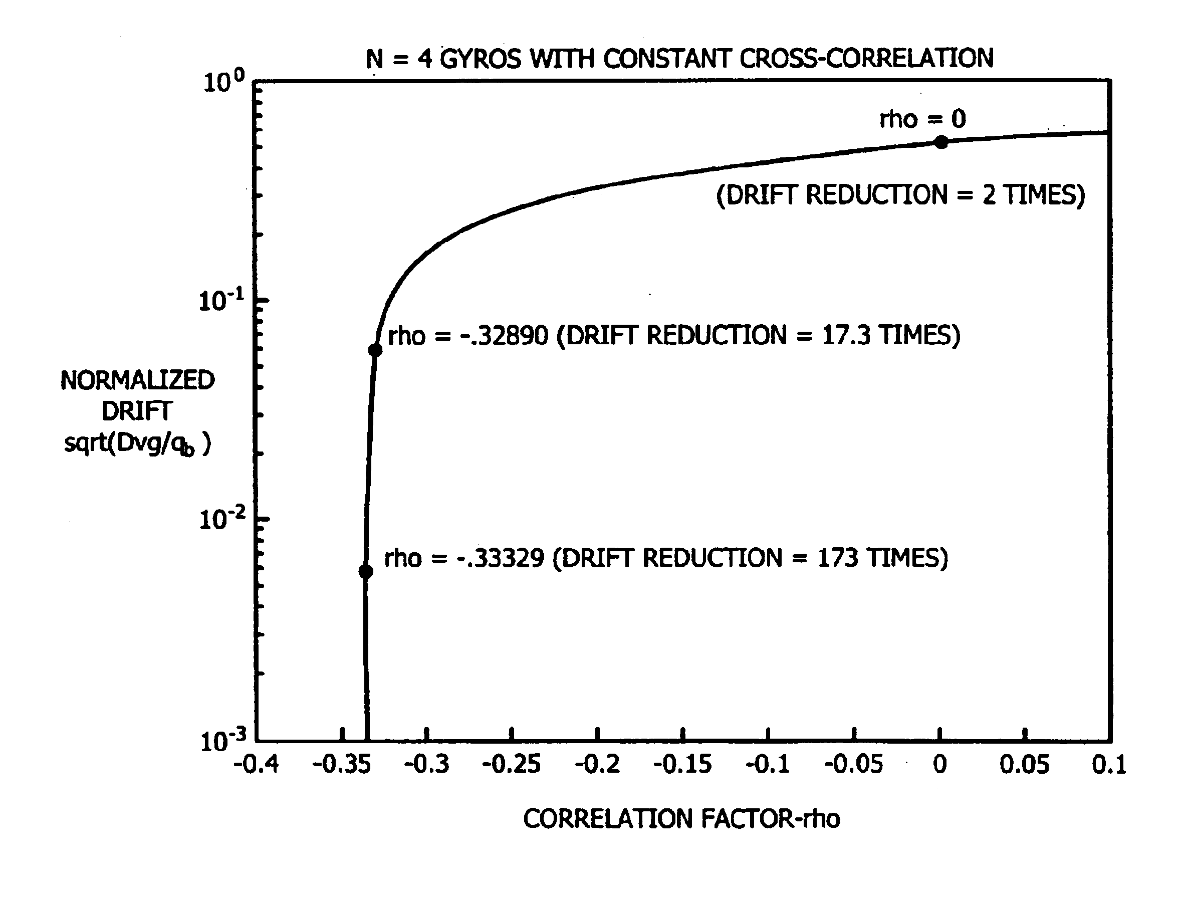
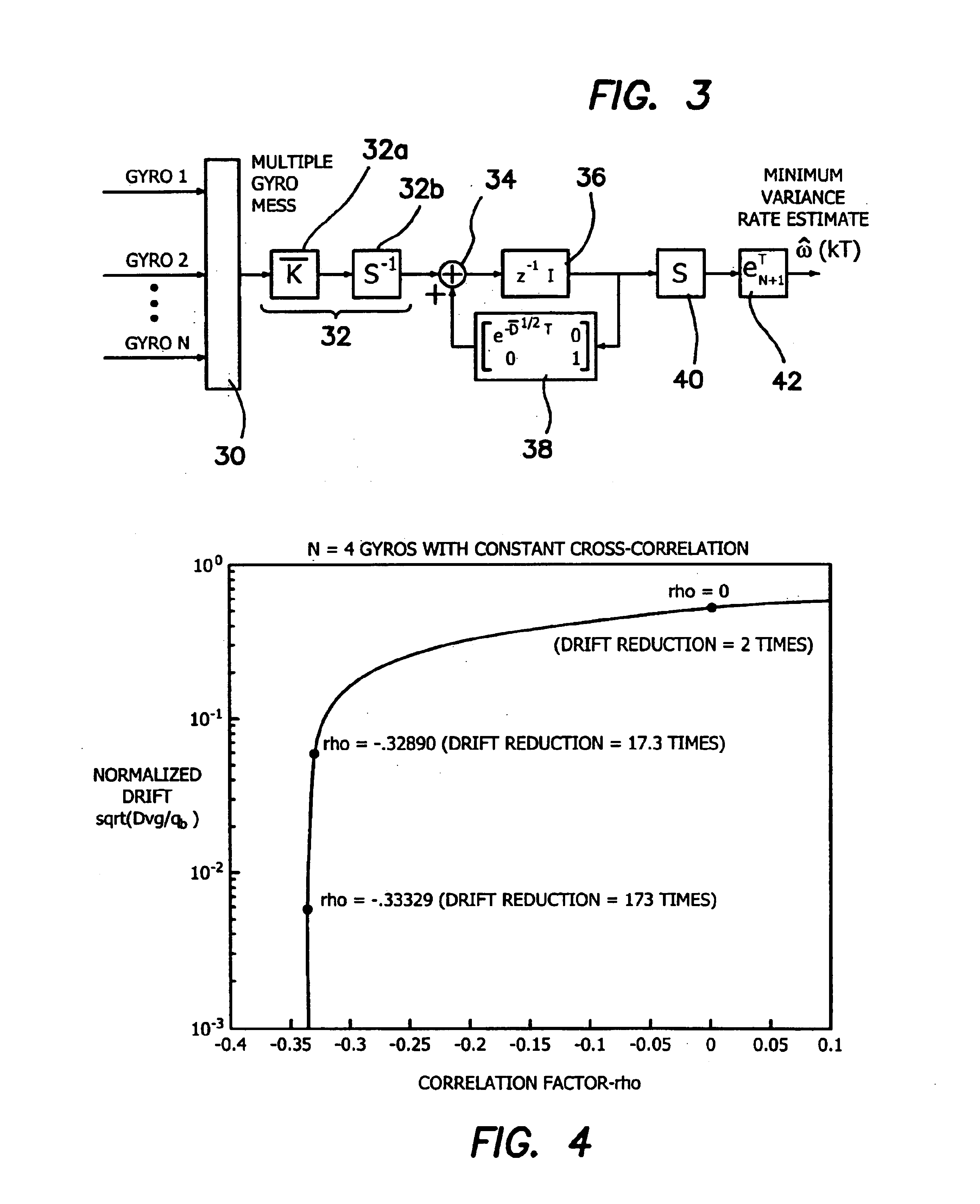
[0073]Some simulation examples will demonstrate the virtual gyro implementation using the optimal digital filter depicted in FIG. 3. All simulations use N=4 gyros, with a sampling rate of T=1 sec, and a total running time of 400,000 secs (approximately 111 hours). The three examples correspond to the choices of the cross correlation factor ρ being set equal to 0; −0.32890; and −0.33329 where it is assumed that all gyros have constant cross-correlation factor ρ. The normalized virtual gyro drift can be calculated by setting N=4 in (5.10) to yield a theoretical expression that predicts that a perfect driftless virtual gyro is obtained in the limit as the correlation factor ρ approaches −⅓. The choices of p are intentionally chosen to successively approach this limiting value. They are plotted in FIG. 4 with a “*”, which shows the normalized virtual gyro drift versus −ρ and the expected drift reduction for each case. Specifically, the expected improvement for each of the choices of ρ c...


PUM


Abstract

An analytical apparatus for optimally combining measurements from N individual rate sensing devices or gyros into a single rate estimate significantly improves performance over that of any individual component device. Kalman filtering is used to combine rate sensed devices optimally in the sense of minimizing the variance of the rate error. The Riccati differential equation (RDE) associated with combining a collection of rate sensed devices is completely and exactly solved to derive to the matrix RDE. This analytic solution serves as the key for understanding all of the theoretical properties of the optimal filter, and provides a complete characterization of the final virtual rate sensed performance. In addition, the analytic RDE solution allows many practical problems to be solved that have proved essential for developing successful filter implementations. A discrete-time minimum variance filter implementation combines sensor measurements optimally.

Description

RELATED APPLICATIONS[0001]The present application is related to U.S. Provisional Patent Application Ser. No. 60 / 362,502, filed on Mar. 6, 2002, which is incorporated herein by reference and to which priority is claimed pursuant to 35 USC 119.BACKGROUND OF THE INVENTION[0002]1. Field of the Invention[0003]The invention relates to the field of gyroscopic instrumentation and in particular to processing the information to improve accuracy of the gyroscopic data.[0004]2. Description of the Prior Art[0005]Small, lightweight, and low-power devices are needed for accurate inertial sensing in a wide range of planned future NASA missions requiring guidance, control and inertial navigation functions (e.g., Mars missions, small body landing, rendezvous and docking, planetary ascent, precision landing, atmospheric entry, aeromaneuvering, aerocapture, etc.). and reduce mass and power requirements in emerging low-cost microspacecraft missions.[0006]Emerging microelectromechanical systems (MEMS) ar...

Claims


Application Information

Patent Timeline
IPC IPC(8): G01C21/10G01C21/16
CPCG01C21/16G01C21/183
Inventor BAYARD, DAVID S.PLOEN, SCOTT R.
Owner CALIFORNIA INST OF TECH
Why Eureka
Try Eureka