
Method of weld repairing a component and component repaired thereby

a technology of metal alloys and components, applied in the direction of manufacturing tools, solvents, transportation and packaging, etc., can solve the problems of linear defects, point defects, ceramic inclusions, pores, etc., and achieve the effect of reducing the risk of cracking

Inactive Publication Date: 2005-04-26
GENERAL ELECTRIC CO
View PDF5 Cites 29 Cited by
  • Summary
  • Abstract
  • Description
  • Claims
  • Application Information

AI Technical Summary

Benefits of technology

[0007]The present invention provides a method of repairing a metal alloy component, such as a superalloy component of a gas turbine engine, and the resulting repaired component. The method employs a filler insert whose size and shape are predetermined so that the welding operation can be carried out to completely melt the insert while minimizing the melting of the surrounding metal alloy component. As such, minimum mixing occurs between the insert and the component, thereby reducing the risk of cracking following the welding operation.
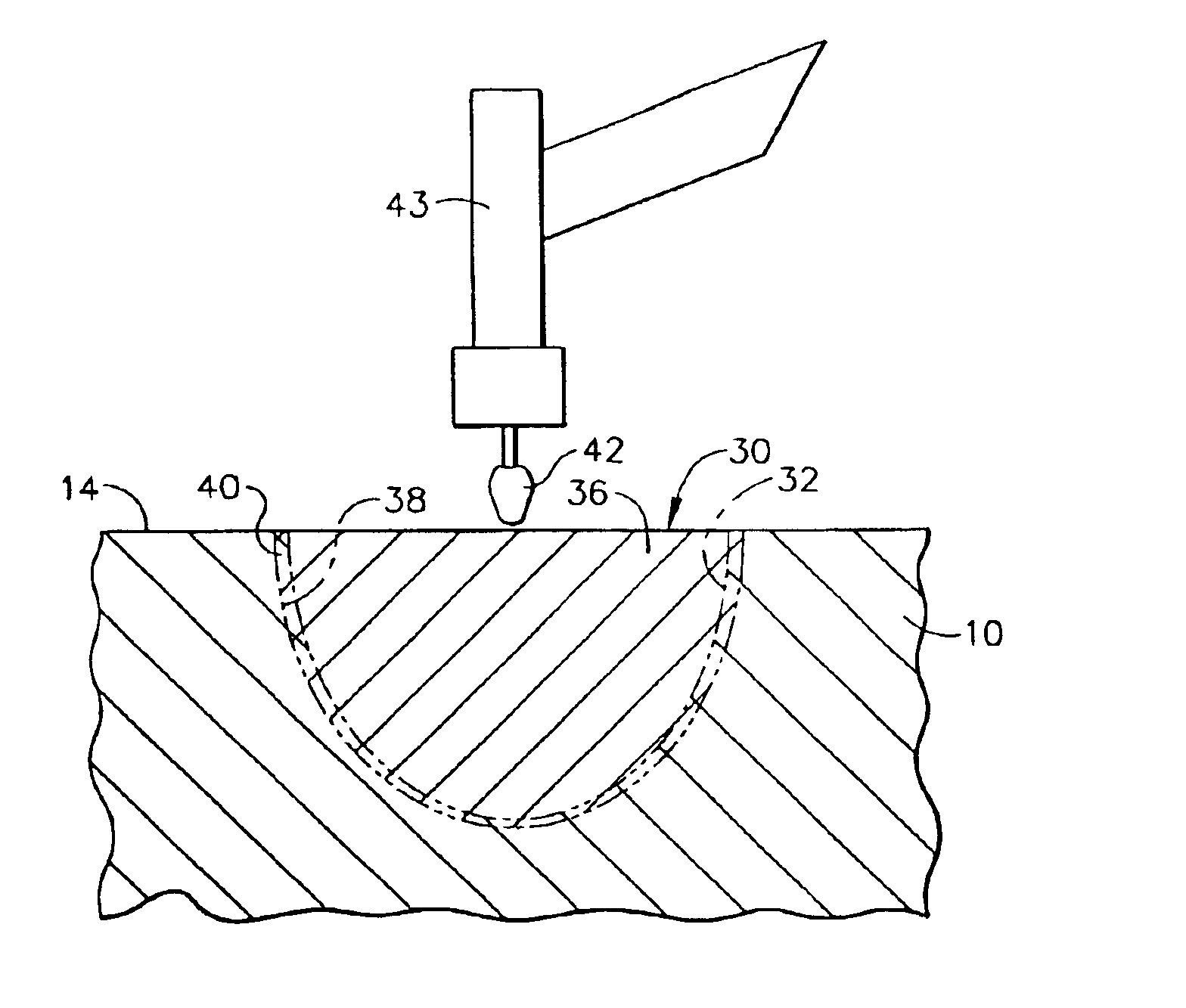
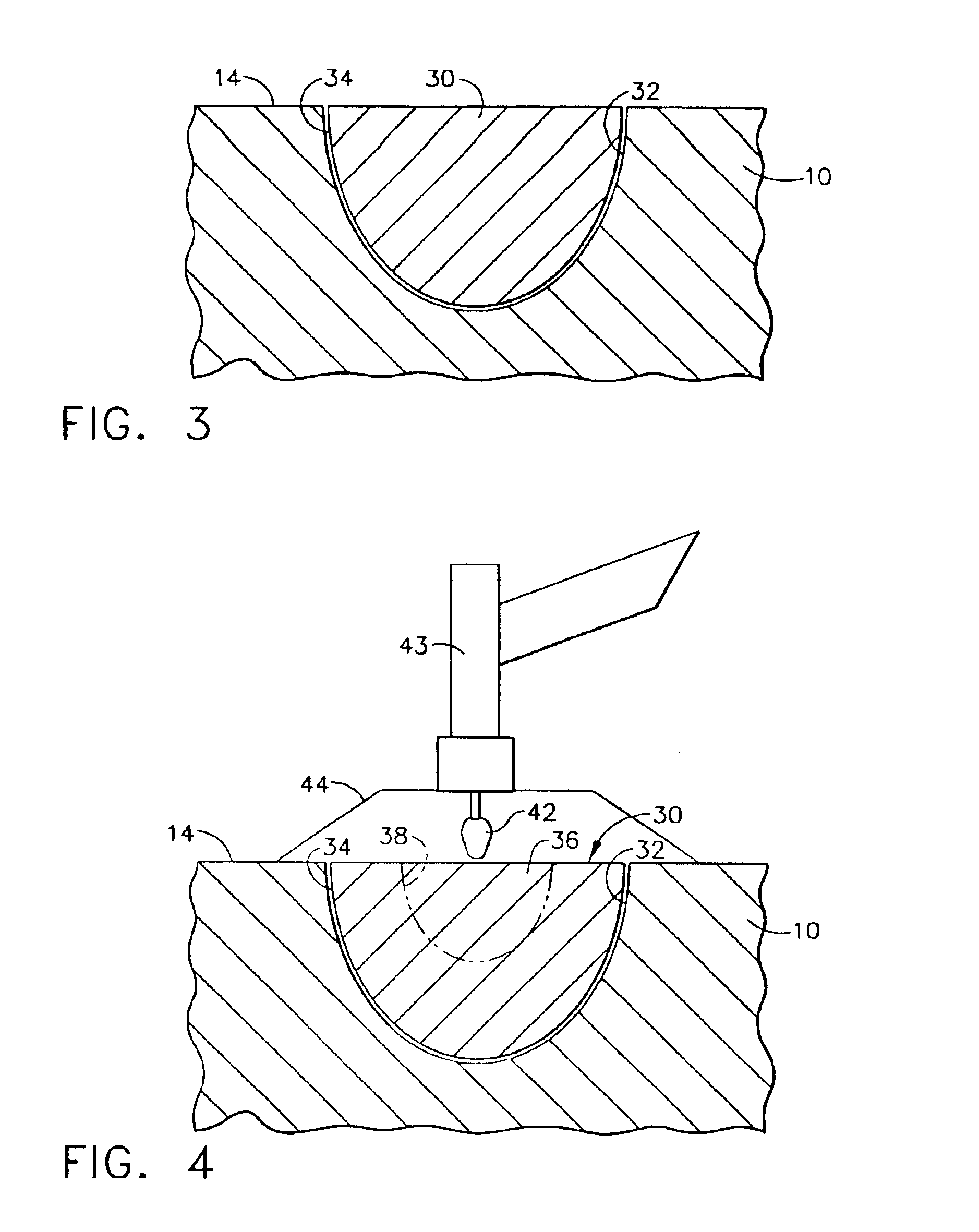
[0009]According to a preferred aspect of the invention, the evaluation is used to determine or estimate the rate at which a melt front propagates through the filler metal alloy, or at least the location of the melt front at different time periods, for a given set of welding conditions and parameters, and this information is used when heating the filler insert so that the melt front that propagates through the insert toward its outer surface will arrive substantially simultaneously at the entire outer surface of the filler insert. Heating may then continue to melt a limited portion of the component beneath the cavity surface, such that the melted portion has a substantially uniform thickness that is intentionally limited to minimize mixing between the materials of the insert and component. As a result, a metal alloy that is relatively difficult to weld, such as a superalloy, can be repaired with an insert formed of an alloy that is more ductile and / or has a lower melting point, yet with a reduced risk of cracking during the welding operation as a result of the reduced amount of mixing in the weld.
[0010]From the above, it will be appreciated that various welding techniques can be employed by the method of this invention, such as a manual arc welder or an electron beam, with the same technique being employed during both the evaluation and the welding operation so that the welding parameters can be used to closely control the amount of melting that occurs during the weld repair operation. Furthermore, the evaluation of a metal alloy can be conducted so that multiple melt pool widths, depths and shapes are correlated with multiple time periods for one or more sets of welding parameters. Multiple filler inserts can then be formed to approximately have the widths, depths and shapes identified during the evaluation, allowing a particular filler insert to be selected based on the size of the defect to be repaired. As such, the repair method of this invention is highly suitable for filling cracks, porosity, flaws and other surface voids or damage that may be present in a metal alloy component, and the composition of the filler insert can be tailored to complement the composition of the component being repaired to yield a strong, crack-free weld repair.

Problems solved by technology

These components are typically used in cast form, and as a result can have point defects, e.g., ceramic inclusions, pores, etc., as well as small linear defects that require repair.
However, temperature resistant materials of the type used in gas turbine engines are inherently resistant to deformation, such that filler materials formed of the same alloy as the component being repaired are difficult to use at room temperature.
A difficulty encountered when using a ductile filler to repair a superalloy component is that the ratio of filler to parent metal is hard to control in manual processes such as TIG.
Frequently, TIG welds of superalloys and other alloys that are difficult to weld will experience cracking in the root passes of the weld due to excessive melting of the parent metal into the molten pool of filler metal.

Method used


Image

  • Method of weld repairing a component and component repaired thereby
  • Method of weld repairing a component and component repaired thereby
  • Method of weld repairing a component and component repaired thereby

Examples


Embodiment Construction

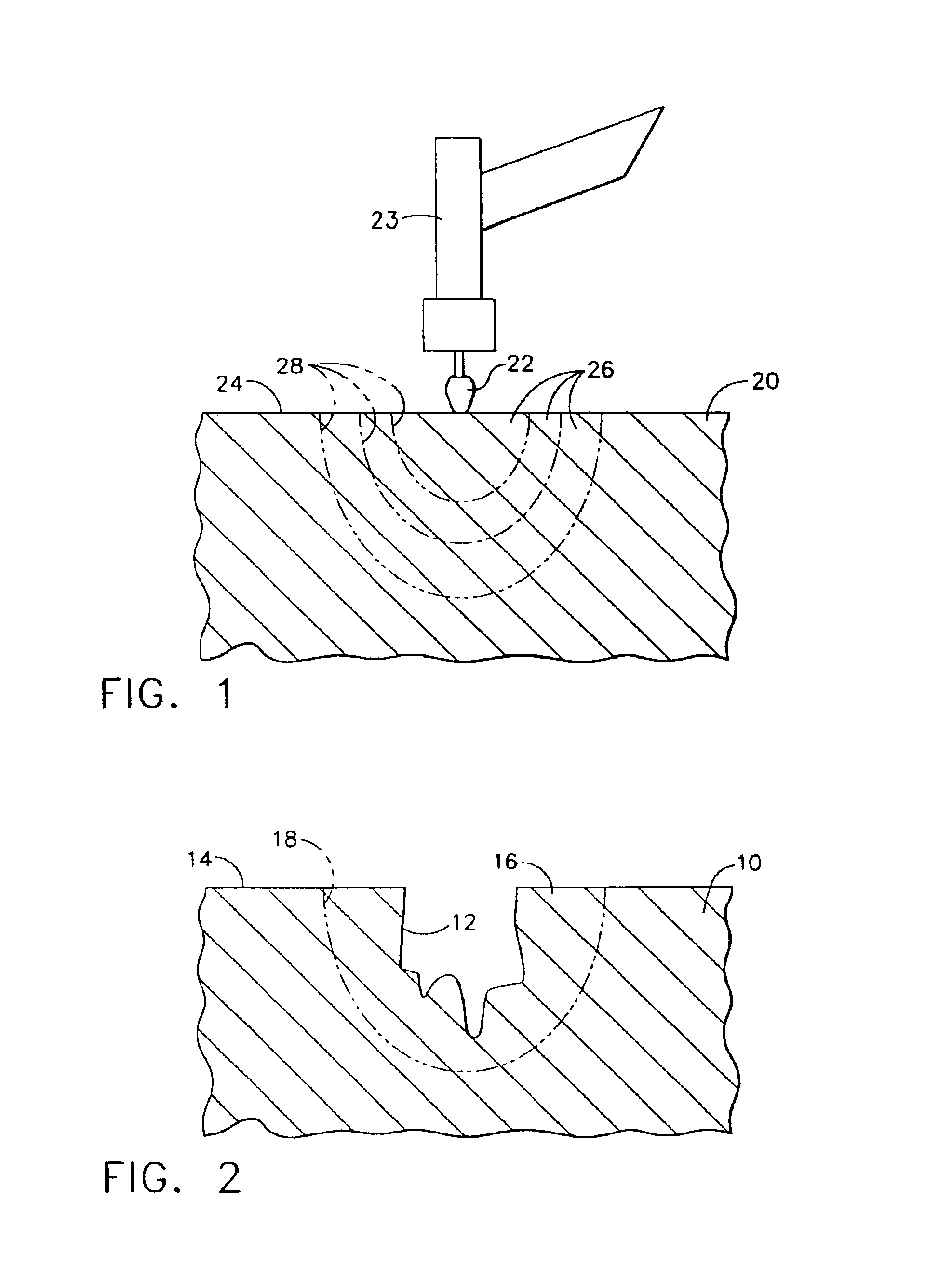
[0015]FIGS. 1 through 5 represent a series of steps carried out to repair a component 10 having a surface defect 12, as represented by FIG. 2. The component 10 may be formed of a variety of metal alloys, including those that are relatively difficult to weld, such as nickel, cobalt and iron-based superalloys used to form cast or forged components of gas turbine engines. If the component 10 is a casting, the defect 12 will typically be a point defect, such as a ceramic inclusion, pore, etc., though the defect 12 could instead be a linear defect.

[0016]Representing a first step of this invention, FIG. 1 shows a surface 24 of a metal alloy body 20 being heated with a torch 22 produced by a TIG welder 23, such that a weld melt pool 26 has developed. As would be expected, the melt pool 26 develops over time along a weld melt front 28 that propagates radially outward and downward through the body 20 from a point nearest the torch 22. The final size and shape of the weld melt pool 26 coincid...


PUM

PropertyMeasurementUnit
Timeaaaaaaaaaa
Thicknessaaaaaaaaaa
Sizeaaaaaaaaaa

Abstract

The method of repairing a metal alloy component, and the resulting repaired component. The method involves machining the component surface to remove a defect, and then placing in the resulting surface cavity a filler insert whose size and shape are predetermined so that the welding operation can be carried out to completely melt the insert while minimizing the melting of the component immediately surrounding the insert. As such, minimum mixing occurs between the materials of the insert and the component, thereby reducing the risk of cracking following the welding operation.

Description

BACKGROUND OF INVENTION[0001]1. Field of the Invention[0002]The present invention generally relates to methods for weld repairing metal alloys, particularly those suitable for use in the high temperature environment of a gas turbine engine. More particularly, this invention relates to a method of performing a controlled weld repair of a defect in a component formed of such an alloy, wherein the method minimizes melting of the alloy with a filler material used to repair the defect.[0003]2. Description of the Related Art[0004]Hot section components of gas turbine engines, such as blades (buckets), vanes (nozzles) and combustors, are typically formed of nickel, cobalt and iron-base superalloys characterized by desirable mechanical properties at turbine operating temperatures. These components are typically used in cast form, and as a result can have point defects, e.g., ceramic inclusions, pores, etc., as well as small linear defects that require repair. Various welding techniques have...

Claims


Application Information

Patent Timeline
IPC IPC(8): B23K9/04B23K9/167B23K9/16B23K26/34B23K31/00B23K33/00
CPCB23K9/04B23P6/005Y10T29/49318B67D1/0081B67D1/06B67D2001/0089
Inventor MURPHY, JOHN THOMAS
Owner GENERAL ELECTRIC CO
Learn More