Arrangement for the optical capture of excited and /or back scattered light beam in a sample

a scattering light beam and optical capture technology, applied in the field of microscopy, can solve the problems of etc., and achieve the effect of reducing the detection sensitivity, increasing the noise of the detector, and increasing the amplification

Inactive Publication Date: 2005-05-03
CARL ZEISS MICROSCOPY GMBH
View PDF8 Cites 18 Cited by
  • Summary
  • Abstract
  • Description
  • Claims
  • Application Information

AI Technical Summary

Benefits of technology

[0035]The quantity of dye signatures that may be used simultaneously, i.e., the quantity of characteristics, for example, of cells that can be investigated simultaneously, can be increased by means of the methods according to the invention. When the spectral signatures of the individual dyes overlap extensively or are very close to one another, the detected wavelength range or numerical aperture must be limited, according to the prior art, for separate detection of the fluorescence signals of individual dyes. This reduces the sensitivity of detection, i.e., increases the noise of the detectors, because greater amplification must be used. This is avoided by the methods and arrangements according to the invention.

Problems solved by technology

This reduces the sensitivity of detection, i.e., increases the noise of the detectors, because greater amplification must be used.

Method used


Image

  • Arrangement for the optical capture of excited and /or back scattered light beam in a sample
  • Arrangement for the optical capture of excited and /or back scattered light beam in a sample
  • Arrangement for the optical capture of excited and /or back scattered light beam in a sample

Examples


Embodiment Construction

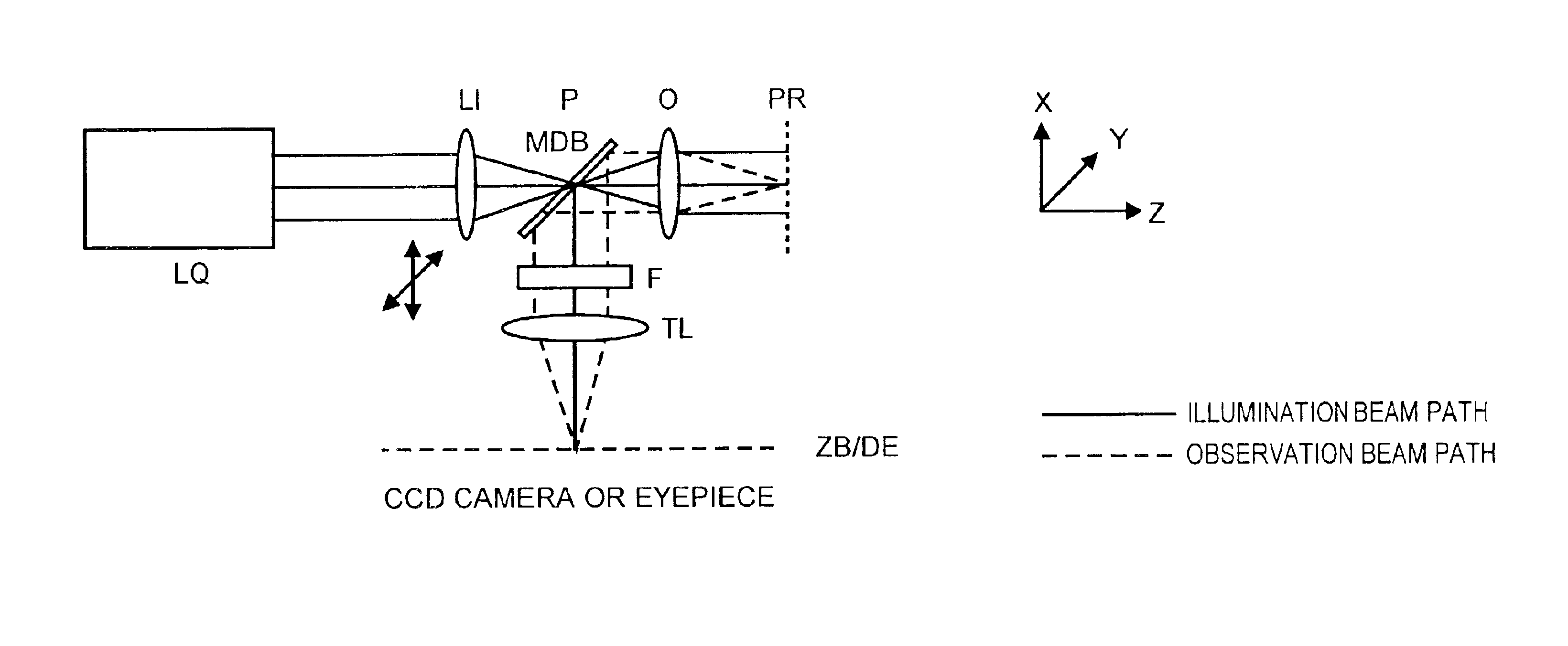
[0053]The following description will amplify upon various arrangements by which the light radiation (hereinafter, detection light) excited and / or backscattered in the specimen can be separated from the excitation light efficiently and independent from wavelength. The arrangements are accordingly suitable in particular for fast multitracking. In the following context, light radiation which is excited in the specimen is light which is radiated from the specimen in an undirected manner, preferably in a large solid angle, particularly fluorescent and luminescent light excited in the specimen.

1. Wide Field Microscope

[0054]The arrangement according to the invention for a wide field microscope is shown schematically in FIG. 4A. In a wide field microscope, the specimen is to be illuminated homogeneously in a plurality of points on the specimen simultaneously in the field to be investigated by a light source usually having a broadband spectrum. For this purpose, the light source LQ is focuse...


PUM

PropertyMeasurementUnit
edge lengthaaaaaaaaaa
wavelengthaaaaaaaaaa
angleaaaaaaaaaa

Abstract

Arrangement for the optical detection of light radiation which is excited and/or backscattered in a specimen in a microscope, wherein the specimen illumination is focused in and/or in the vicinity of a pupil plane of the beam path between the specimen plane and detection plane and apparatus is provided in this plane for spatially separating the illumination light from the detection light, wherein fluorescent light and/or luminescent light and/or phosphorescent light and/or diffusely scattered illumination light coming from the specimen is detected, and the apparatus for spatial separation comprises at least a reflecting first portion and at least a transmitting second portion, wherein the reflecting portion serves to couple in the illumination light and the transmitting portion serves to pass the detection light in the detection direction or the transmitting portion serves to couple in the illumination light and the reflecting portion serves to couple out the detection light.

Description

CROSS-REFERENCE TO RELATED APPLICATIONS[0001]This application claims priority of German application No. 101 60 976.0, filed Dec. 10, 2001, the complete disclosure of which is hereby incorporated by reference.BACKGROUND OF THE INVENTION[0002]a) Field of the Invention[0003]The invention is directed to a method in microscopy, particularly fluorescence microscopy, laser scanning microscopy, fluorescence correlation spectroscopy, and near-field scanning microscopy, for the investigation of predominantly biological specimens, preparations and associated components. This includes methods for screening active ingredients (high throughput screening) based on fluorescence detection. Therefore, simultaneous investigations of specimens with multiple fluorophores in real time by means of simultaneous illumination of the specimen in a plurality of points on the specimen are possible with overlapping fluorescence spectra also in three-dimensional structures of thick specimens.[0004]b) Description ...

Claims


Application Information

Patent Timeline
Patent Type & Authority Patents(United States)
IPC IPC(8): G02B21/00G02B21/16G02B21/06G01N21/64G02B21/36G02B26/10G02B27/28
CPCG02B21/0032G02B21/0076G02B27/58G02B21/16G02B21/06
Inventor WOLLESCHENSKY, RALFKEMPE, MICHAEL
Owner CARL ZEISS MICROSCOPY GMBH
Why Eureka
Try Eureka