Positioning device

Inactive Publication Date: 2005-05-03
TROST DAVID
View PDF9 Cites 4 Cited by
  • Summary
  • Abstract
  • Description
  • Claims
  • Application Information

AI Technical Summary

Benefits of technology

[0018]The metrology component, typically a mirror, is mounted to the magnet assembly and the gas bearing or bearings. The metrology component may be mounted to these other components such that it is fixed with respect to them, or such that it can move with respect to them in any or all of the remaining three degrees of freedom (θx, θy, and Z). These are referred to as the “out-of-plane” degrees of freedom. In any event, the metrology component is mounted to the magnet assembly in such a way that as direct and rigid a connection as is practical is maintained between the magnet assembly and the mirror in the in-plane degrees of freedom. In this way, when Lorentz forces cause the magnet assembly to move in any of these degrees of freedom, the frequencies of the resonant modes of vibration between the magnet assembly and the metrology component that most affects their relationship in these degrees of freedom are maximized. This allows the metrology component to follow the motion of the magnet assembly with the highest possible fidelity, resulting in better stage performance.
[0019]Similarly, in the out-of-plane degrees of freedom, the metrology component is connected to the gas bearings in the most direct way practical. The gas bearings are elements that are constrained to move in the plane of motion defined by the coil assembly. The metrology component is therefore referenced to the gas bearings in the most direct manner possible in the out-of-plane degrees of freedom. In the event that the stage has no capability to move in the out-of-plane degrees of freedom, the mirror is connected to the gas bearings in the most rigid manner practical. In the event that the stage is intended to move in the out-of-plane degrees of freedom, it incorporates an actuator such as a voice coil, piezoelectric device, or screw for each of the desired degrees of freedom. These actuators are on one end attached as directly as possible to the gas bearing, and on the other end, as directly as possible to the metrology component. This maximizes the fidelity of the motion of the metrology component in the out-of-plane degrees of freedom. It is also necessary that the six constraints described above (X, Y, Z, θx, θy, θz) are implemented in such a way that they do not cause the metrology component to distort since distortion of the metrology component can lead to errors in measurement of the stage position. Mounts of this type that are capable of rigid constraint while minimizing distortion are known to those skilled in the art as kinematic mounts.
[0020]The use of plane gas bearings has several useful benefits. One of them is that the stage can be built with a minimum number of bearings. As few as one gas bearing may be used, although for practical reasons more may be desired. Minimizing the number and size of gas bearings is particularly useful when there is intent to operate the stage in vacuum, as this minimizes the leakage of gas from the bearings into the vacuum environment.
[0021]In some applications in the semiconductor industry, an object such as a silicon wafer or a reticle substrate is mounted to the metrology component. The system can be sensitive to stray magnetic fields in this location that are generated by the magnets and coils. In some embodiments of this invention, the design is optimized to reduce these stray fields. This is accomplished through the use of high permeability material for the soft iron components of the magnet assembly. In addition, moving magnetic shielding material may be added to further shield from stray fields.

Problems solved by technology

This resulted in modes of resonance at lower frequencies than desirable as well as friction, backlash, and other inaccuracies of movement.
This distortion makes the use of air bearings at a feed through difficult.

Method used


Image

  • Positioning device
  • Positioning device
  • Positioning device

Examples


Embodiment Construction

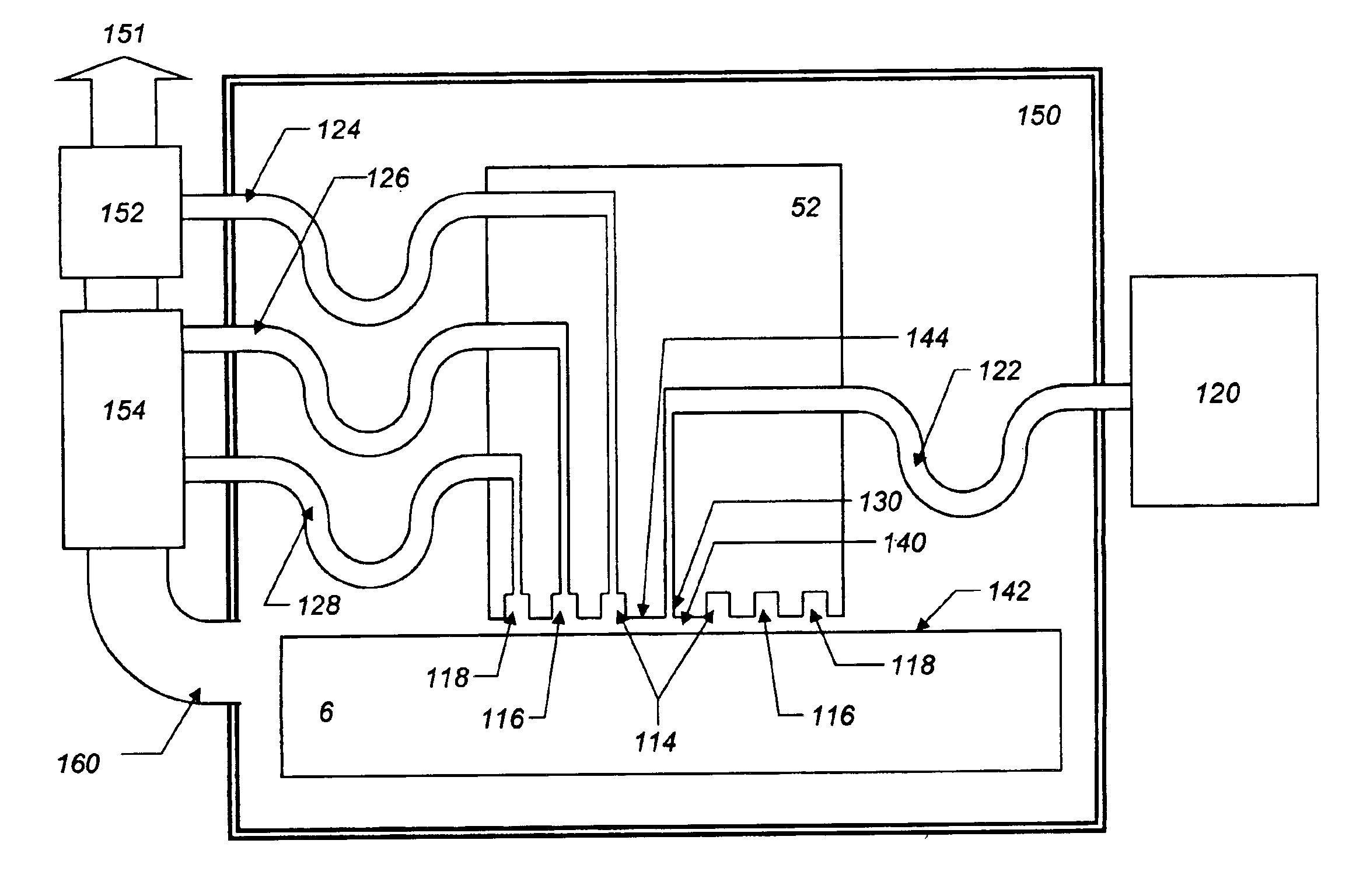
[0034]The preferred embodiment includes a base structure 6 (FIG. 3), which forms the stage stator. This is the part of the stage that is nominally stationary. The base structure 6 includes a rigid structural base plate 8, to which are mounted two coil assemblies 10 and 11. Each coil assembly consists of a soft magnetic core 12, which readily conducts magnetic flux, and a pair of wire coils 14 and 16 wound in orthogonal directions about the core. A connector made of soft magnetic material 18 creates a magnetic flux bridge between the cores of the two coil assemblies. A plate of nonmagnetic and nonconducting material 19 (shown as transparent to reveal the coil assemblies) covers the coils to provide a hard, smooth and nominally flat surface for the movable portion of the gas bearings to glide on.

[0035]The moving part of the stage, referred to as the carriage 20 (FIGS. 2, 2a), contains two permanent magnets 30 and 32, one with its north pole facing a coil assembly, and the other with i...


PUM


Abstract

This invention is directed to precision positioning devices which are well suited to manufacturing and inspection of semiconductor devices. A pair of coil assembles are attached to a base plate. The base plate forms a static portion of a gas bearing assembly. A carriage assembly, forming a movable portion of the gas bearing assembly, is capable of in-plane motion over the coil assembly. The carriage assembly contains permanent magnets and a soft magnetic bridge. A metrology component, such as a mirror, is attached to the carriage kinematically. Three in-plane constraints consist of substantially straight line connections between the metrology component and the carriage in a plane substantially parallel to the plane of motion of the gas bearings. Three out-of-plane constraints on the metrology component comprise substantially straight line connections between it and the gas bearings. The positioning device is operable in vacuum by directing the flow of gas out of the bearings to a vacuum pump. The positioning device is further capable of creating an area of low stray magnetic fields through the use of moving magnetic shielding material.

Description

FIELD OF THE INVENTION[0001]This invention relates to gas bearings comprising a carriage assembly and a static base assembly and, in particular, to a gas bearing articulated stage that is for use in a vacuum environment such as in a semiconductor wafer process chamber.BACKGROUND OF THE INVENTION[0002]This invention relates to a positioning device, also called a stage, for placing an object in a precise position, or for moving an object with precision. Devices of this kind have myriad applications and are of particular use in the manufacturing of semiconductors. Semiconductor manufacturing processes that involve the use of stages can include: lithography, inspection, pattern generation, wire bonding and others. In recent years, newer forms of many of these processes are performed in vacuum and require an environment with very low stray magnetic fields. This invention is especially suitable to these applications.[0003]With traditional stages, in order to move an object in three or mor...

Claims


Application Information

Patent Timeline
IPC IPC(8): G03F7/20H01L21/68H01L21/67
CPCF16C29/025F16C32/0603F16C32/0666F16C33/748H01L21/68G03F7/70758G03F7/70816G03F7/70941H01J2237/20F16C2300/62
Inventor TROST, DAVID
Owner TROST DAVID
Why Eureka
Try Eureka