Method of making a composite electric machine component of a desired magnetic pattern

a technology of composite electric machines and rotors, applied in the direction of magnets, magnetic circuit shapes/forms/construction, magnetic bodies, etc., can solve the problems of limiting the performance of electric machines, reducing the operating speed, and weak structural properties of synchronous reluctance rotors formed from stacked axial laminations, so as to achieve less cost, more output power, and speed up the effect of spin

Inactive Publication Date: 2005-05-10
DELPHI TECH INC
View PDF14 Cites 40 Cited by
  • Summary
  • Abstract
  • Description
  • Claims
  • Application Information

AI Technical Summary

Benefits of technology

[0010]In an exemplary embodiment for forming a rotor assembly, the segments are positioned to form a disk having the desired magnetic pattern, and a plurality of sinterbonded disks are stacked on a shaft with their magnetic patterns aligned. In an embodiment of the present invention, permanent magnets may be affixed to the composite component to form a permanent magnet electric machine component. Alternatively, permanent magnet segments may be formed to a green strength by pressing hard ferromagnetic powder metal in a die of desired shape, and then placing the permanent magnet segments in the desired magnetic pattern followed by sintering and magnetizing to form a permanent magnet electric machine component. By the method of the present invention, there is provided a structurally robust electric machine component having definite boundaries between magnetic regions that costs less, spins faster, provides more output power, and is more efficient.

Problems solved by technology

When the shape of the laminations and / or the additional winding / permanent magnet components are compromised, reduced operating speed and flux leakage may occur, thus limiting performance of the electric machine.
By way of example, synchronous reluctance rotors formed from stacked axial laminations are structurally weak due to problems associated both with the fastening together of the laminations and with shifting of the laminations during operation of their many circumferentially discontinuous components.
This results in a drastically lower top speed.
This results in both structural weakness due to the small slot supports and reduced output power due to magnetic flux leakage through the slot supports.
Doing so permits the use of completely non-magnetic structural supports that not only provide the additional strength to allow the rotors to spin faster, for example up to 80% faster, but also virtually eliminate the flux leakage paths that the traditionally manufactured electric machines must include to ensure rotor integrity, but which lead to reduced power output and lower efficiency.
One disadvantage of this compaction process is that the mixing that occurs after the die insert is removed can lead to blurred boundaries between permeable and non-permeable materials thereby reducing performance.
Further, the blurring of boundaries is often particularly pronounced near the top and bottom of the pressed disks such that these sections of the machine do not adequately perform their intended function.
However, the injection molding process can be expensive because liquifying the metals generally requires the use of powders that are more expensive and of finer grain size than the powders that can be used in the compaction process.
Thus, composite metal injection molding may not be cost effective for a broad range of electric machine applications.

Method used


Image

  • Method of making a composite electric machine component of a desired magnetic pattern
  • Method of making a composite electric machine component of a desired magnetic pattern
  • Method of making a composite electric machine component of a desired magnetic pattern

Examples


Embodiment Construction

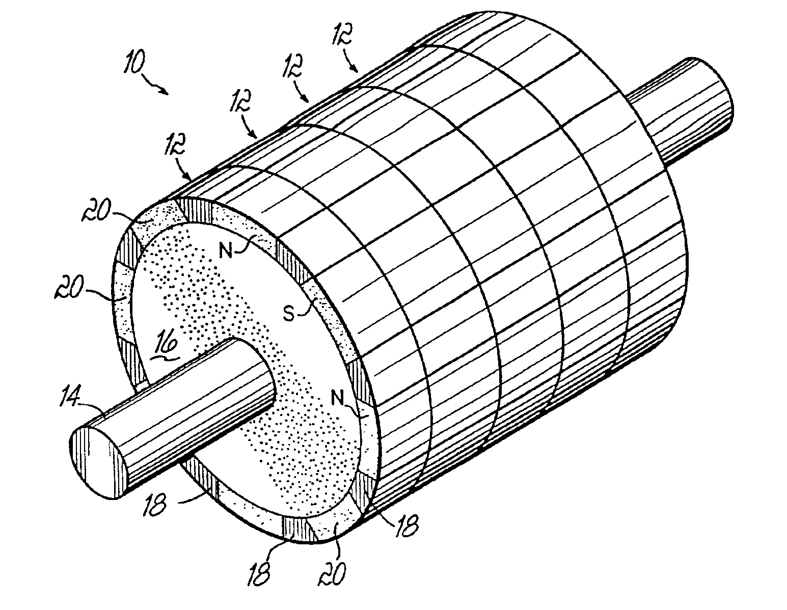
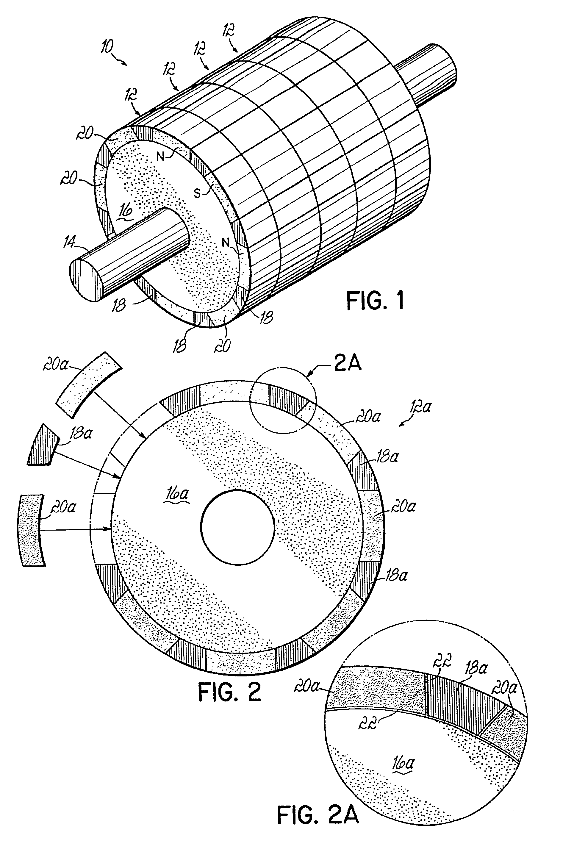
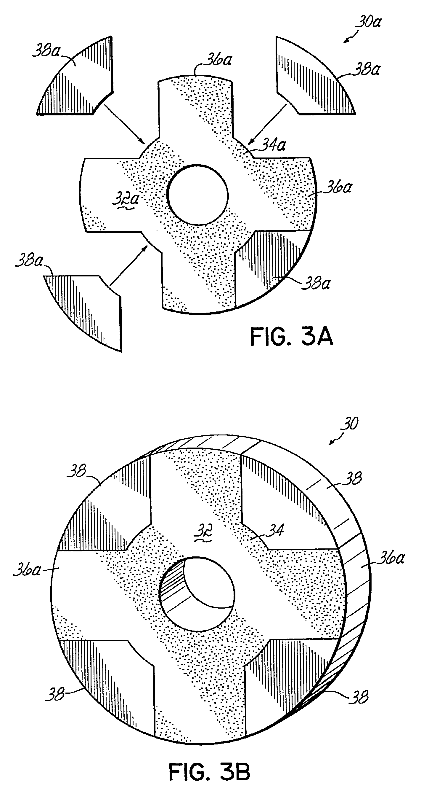
[0026]The present invention is directed to sinterbonding electric machine components by pressing magnetically conducting and magnetically non-conducting rotor or stator segments separately to a green state, arranging the green-strength segments adjacent to each other with a small amount of powder material in between green-strength segments, and then sintering the whole assembly. The small amount of powder material, such as high purity iron powder, facilitates bond formation between the separate green-strength segments during sintering. By way of example and not limitation, the sinterbonding process of the present invention may be used on induction, permanent magnet, switched reluctance and synchronous reluctance rotors, as well as permanent magnet and reluctant sensor wheels. Sinterbonding combines the cost advantage of composite powder metal compaction manufacturing processing with the performance advantage of metal injection molding processing by allowing the magnetically conducti...


PUM

PropertyMeasurementUnit
outer diameteraaaaaaaaaa

Abstract

A method of making composite electric machine components. Magnetic segments and non-magnetic segments are separately formed to green strength, and then arranged adjacent to each other in a desired magnetic pattern. A small amount of powder material is added in-between the segments, and the whole assembly is then sintered to form a sinterbonded composite component of high structural integrity.

Description

FIELD OF THE INVENTION[0001]This invention relates generally to composite electric machine rotor components and rotor sense parts, and more particularly, to the manufacture of rotor components and rotor sense parts by sinterbonding.BACKGROUND OF THE INVENTION[0002]It is to be understood that the present invention is equally applicable in the context of generators as well as motors. However, to simplify the description that follows, reference to a motor should also be understood to include generators.[0003]In the field of electric machine rotor cores, stator cores and generators, the machine cores are typically constructed using laminations stamped from electrical steel. The laminations are stacked and pressed onto a shaft. Then, in most electric machines, windings or permanent magnets are added. These laminations are configured to provide a machine having magnetic, non-magnetic, plastic and / or permanent magnet regions to provide the flux paths and magnetic barriers necessary for ope...

Claims


Application Information

Patent Timeline
Patent Type & Authority Patents(United States)
IPC IPC(8): B22F7/06H01F41/02H02K1/00H02K1/27H02K1/02H02K15/02H02K15/03
CPCB22F7/064H02K1/02H02K1/278H02K15/02H02K15/03H01F41/0246Y10T29/49163H01F41/028Y10T29/49078Y10T29/49009Y10T29/49012Y10T29/49075Y10T29/49011Y10T29/53143Y10T29/49073Y10T29/49076Y10T29/49071
Inventor REITER, JR., FREDERICK B.STUART, TOM L.
Owner DELPHI TECH INC
Why Eureka
Try Eureka