
Laminated piezoelectric element, actuator and printing head

a piezoelectric element and actuator technology, applied in piezoelectric/electrostrictive/magnetostrictive devices, piezoelectric/electrostriction/magnetostriction machines, printing, etc., can solve the problems of significant deformation, marked decrease in the displacement of the printing head, and inability to achieve large displacement, etc., to achieve better displacement characteristics, less variation in displacement, and large displacement

Active Publication Date: 2005-05-10
KYOCERA CORP
View PDF9 Cites 9 Cited by
  • Summary
  • Abstract
  • Description
  • Claims
  • Application Information

AI Technical Summary

Benefits of technology

[0011]Accordingly, an advantage of the present invention is to provide a laminated piezoelectric element and an actuator that are capable of making larger displacement with less variation in the displacement.

Problems solved by technology

Unfortunately, the conventional actuator is relatively large in thickness which imposes a limitation to the amount of displacement, resulting in a problem that large displacement cannot be achieved.
Moreover, there is also a problem of deteriorating characteristics of the actuator displacement, thus resulting in a marked decrease in the displacement of the printing head.
In the case of a thin actuator made by stacking piezoelectric ceramic layers each measuring several tens of micrometers or less in thickness or an actuator having a total thickness of 100 μm or less, on the other hand, there is such a problem that shrinkage of the internal electrodes caused during sintering results in significant deformation because the actuator is very thin.
There is also such a problem that the d constant varies significantly across a single element, since residual stress is distributed unevenly across the actuator by uneven shrinkage of the internal electrodes.
It requires an expensive IC to control the operation of the actuators having such significant variations, thus resulting in an increase in the manufacturing cost of the printing head or the printer, while requiring complicated control scheme.

Method used


Image

  • Laminated piezoelectric element, actuator and printing head
  • Laminated piezoelectric element, actuator and printing head
  • Laminated piezoelectric element, actuator and printing head

Examples


example 1

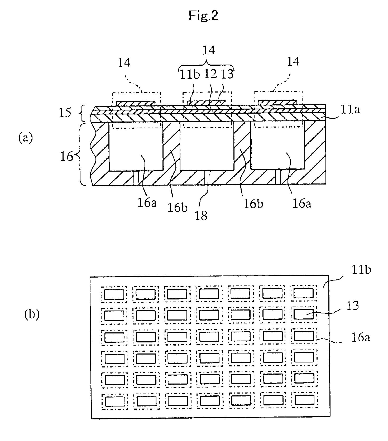
[0064]The laminated piezoelectric element of the present invention was fabricated and was applied to an ink jet printing head as an actuator.

[0065]First, a powder of piezoelectric ceramic material containing lead zirconate titanate (PZT) having a purity of 99% or higher was prepared as the starting material.

[0066]The piezoelectric ceramic powder was mixed with butyl methacrylate used as an aqueous binder, ammonium polycarbonate used as a dispersant and isopropyl alcohol and water used as solvents, to obtain a slurry. The slurry was spread over a carrier film by means of a doctor blade, so as to form a green sheet having a thickness of 30 μm.

[0067]Then a paste to form the internal electrode was made by mixing a Ag—Pd alloy containing silver and palladium in proportions shown in Table 1 and the piezoelectric ceramic powder containing PZT as the main component, thereby to obtain the composition of the internal electrode shown in Table 1. The Ag—Pd alloy and the piezoelectric ceramic po...

example 2

[0080]High purity powders of Pb2O3, ZrO2, TiO2, BaCO3, ZnO, SrCO3, Sb2O3, NiO, TeO2 were prepared as the stock materials. Predetermined quantities of these powders were measured to obtain the compositions A1 to D1 described below after sintering.[0081][A1]: Pb1−x−ySrxBay(Zr1 / 3Sb2 / 3)a(Ni1 / 2Te1 / 2)bZr1−a−b−cTicO3(x=0.04, y=0.02, a=0.075b=0.005, c=0.45)[0082][B1]: Pb(Zn1 / 3Sb2 / 3)0.075(Ni1 / 3Te1 / 2)0.005Zr0.47Ti0.04O3 [0083][C1]: PbZr0.5Ti0.5O3 [0084][D1]: BaTiO3

[0085]The predetermined quantities of the powders measured as described above were mixed in a wet process in a ball mill for 20 hours, and the mixture was dewatered and dried. The dried mixture was calcined at 900° C. for three hours, and the calcined material was crushed in a wet process in a ball mill.

[0086]The crushed material was mixed with an organic binder, water, a dispersant and a plasticizer to make a slurry. The slurry was formed into a sheet by the roll coater process that is commonly employed when forming a thin green s...


PUM

PropertyMeasurementUnit
thicknessaaaaaaaaaa
mean crystal grain sizeaaaaaaaaaa
thicknessaaaaaaaaaa

Abstract

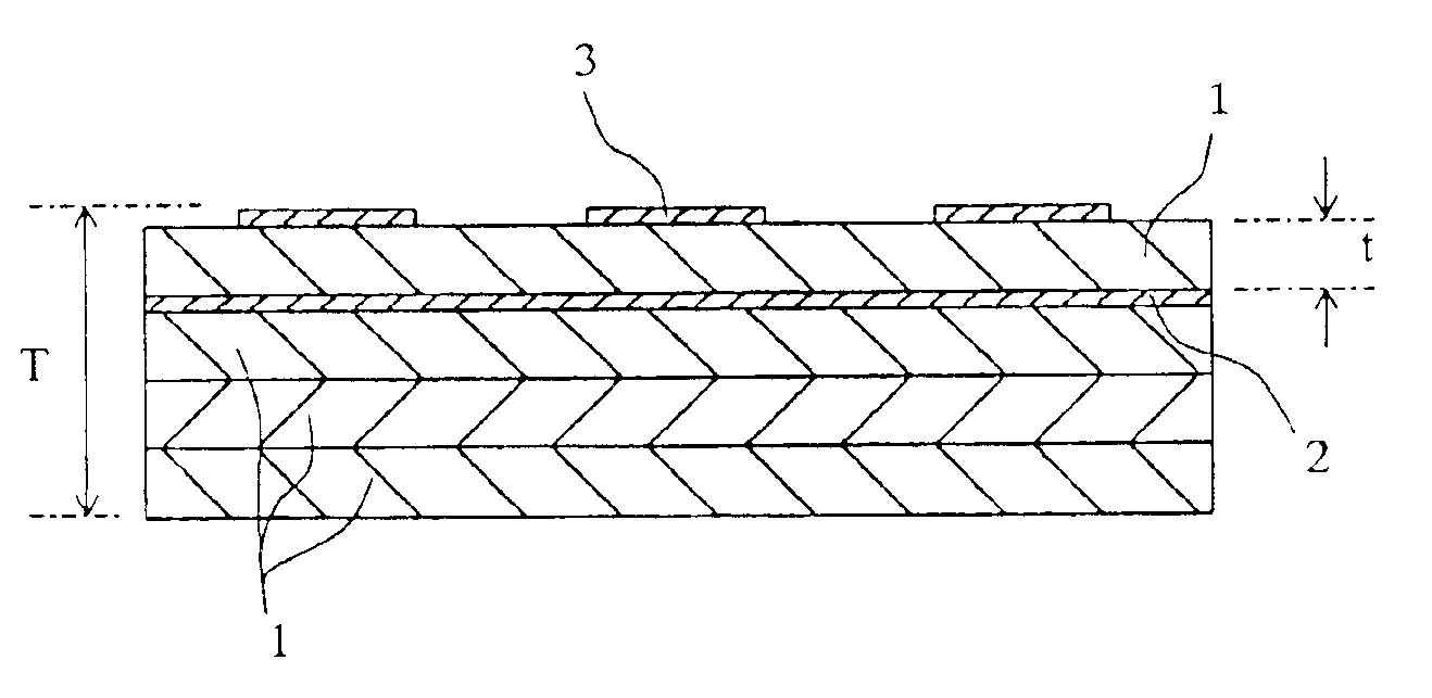
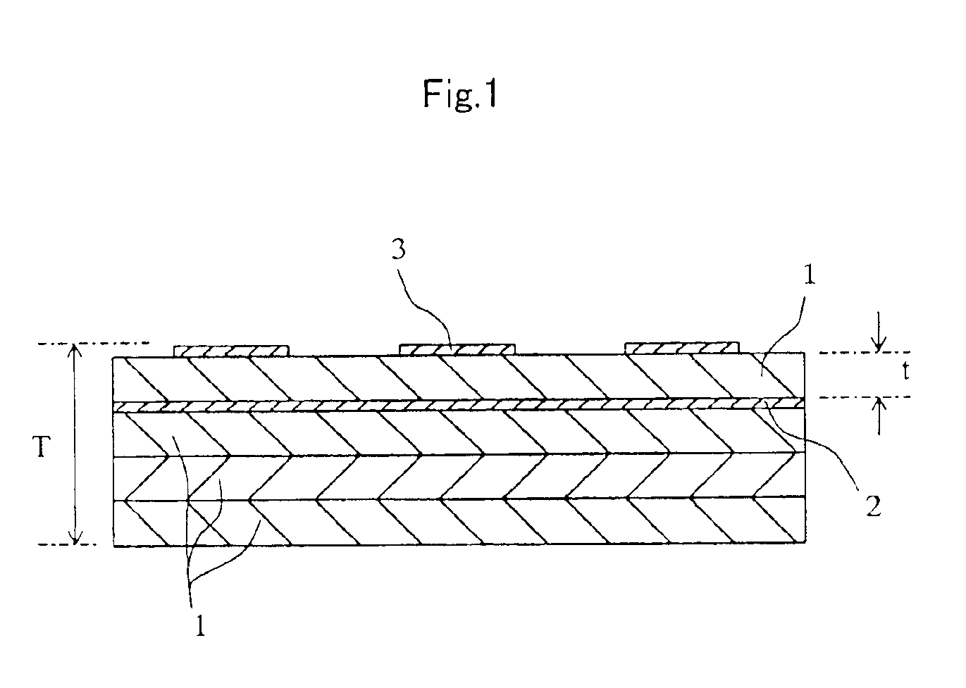
The laminated piezoelectric element having a thickness of 100 μm or less of the present invention comprises a laminate which comprises a plurality of piezoelectric ceramic layers 1, and electrodes 2,3 provided the surface and the inside of the laminate, wherein the electrode 2 comprises a silver-palladium alloy containing 71 to 99.9% by volume of silver and 0.1 to 29% by volume of palladium.

Description

BACKGROUND OF THE INVENTION[0001]1. Field of the Invention[0002]The present invention relates to a laminated piezoelectric element, an actuator and a printing head and, more particularly, to a laminated piezoelectric element and an actuator that are suitable for the piezoelectric sensor of, for example, a fuel injector, an ink jet printer, a piezoelectric resonator, an oscillator, an ultrasonic motor, an ultrasonic oscillator, a filter, an acceleration sensor, a knocking sensor, an AE sensor or the like, and can be advantageously used particularly for a printing head that utilizes vibration of a 2-dimensional vibration of expansion and contraction or linear vibration in the longitudinal direction or in the direction of the thickness.[0003]2. Description of Related Art[0004]Piezoelectric ceramics materials have been used in, for example, an actuator, a filter, a piezoelectric resonator (oscillator included), an ultrasonic oscillator, an ultrasonic motor and a piezoelectric sensor.[00...

Claims


Application Information

Patent Timeline
Patent Type & Authority Patents(United States)
IPC IPC(8): B41J2/14B41J2/16H01L41/00H01L41/047H01L41/09B41J2/045B41J2/055H01L41/083H01L41/187
CPCB41J2/14233B41J2/161B41J2/1623B41J2/1632H01L41/0973H01L41/0477B41J2/1642B41J2002/14266B41J2002/14459B41J2202/03H10N30/877H10N30/2047
Inventor YUU, YOSHIHIROIWASHITA, SHUZOTAKAHASHI, DAISUKE
Owner KYOCERA CORP
Learn More