Exhaust gas reflux apparatus for internal combustion engine

Inactive Publication Date: 2005-05-17
HONDA MOTOR CO LTD
View PDF8 Cites 11 Cited by
  • Summary
  • Abstract
  • Description
  • Claims
  • Application Information

AI Technical Summary

Benefits of technology

[0008]According to the first feature, when exhaust gas reflux is required, the actuator is used to move the one-way connection means to the operating position during an intake stroke, and thus the exhaust rocker arm is driven from the intake rocker arm to open the exhaust valve to suck an exhaust gas into a combustion chamber from an exhaust port. In this case, during an exhaust stroke, the one-way connection means does not interfere with rocking of the exhaust rocker arm, causing no problem in opening and closing of the exhaust valve. When the exhaust gas reflux is not required, the one-way connection means is returned to the non-operating position, to thereby avoid interference between the intake rocker arm and the exhaust rocker arm. Therefore, as compared with a conventional apparatus having a special exhaust gas reflux valve, opening areas of an intake port and the exhaust port opening into a ceiling surface of the combustion chamber can be increased, to thereby improve output performance of the internal combustion engine. Besides, a simple configuration can be obtained since there is no increase in the number of valves.
[0010]According to the second feature, the actuator is not operated and the exhaust gas reflux is not performed in an area from a fully-closed position to a predetermined low opening degree and an area with a predetermined high opening degree or more, other than the middle opening degree area of the throttle valve, thus allowing stable combustion and reduction in fuel consumption during low speed operation including idling of the internal combustion engine, and securing high output during high load operation.
[0012]According to the third feature, the one-way connection means having a simple configuration is used to drive the exhaust rocker arm from the intake rocker arm to reflux the exhaust gas, thus providing an inexpensive exhaust gas reflux apparatus.
[0014]According to the fourth feature, the valve opening lift of the exhaust valve by the one-way connection means can be controlled depending on the engine load, and thus the amount of exhaust gas refluxed into the combustion chamber is adjusted depending on the engine load, to thereby allow stable combustion and reduction in NOx concentration in the exhaust gas.
[0016]According to the fifth feature, the one-way connection means having a simple configuration is used to drive the exhaust rocker arm from the intake rocker arm, to thereby reflux the exhaust gas and adjust the amount of refluxed exhaust gas depending on the engine load.

Problems solved by technology

Such a construction of the exhaust gas reflux apparatus for an internal combustion engine has a problem in output performance of the engine, since a cylinder head requires a specific exhaust gas reflux valve besides an intake valve and an exhaust valve generally used, and the exhaust gas reflux valve prevents provision of sufficiently large opening areas of an intake port and an exhaust port opening into a limited ceiling surface area of the combustion chamber.

Method used


Image

  • Exhaust gas reflux apparatus for internal combustion engine
  • Exhaust gas reflux apparatus for internal combustion engine
  • Exhaust gas reflux apparatus for internal combustion engine

Examples


first embodiment

[0037]First, the invention shown in FIGS. 1 to 16 will be described.

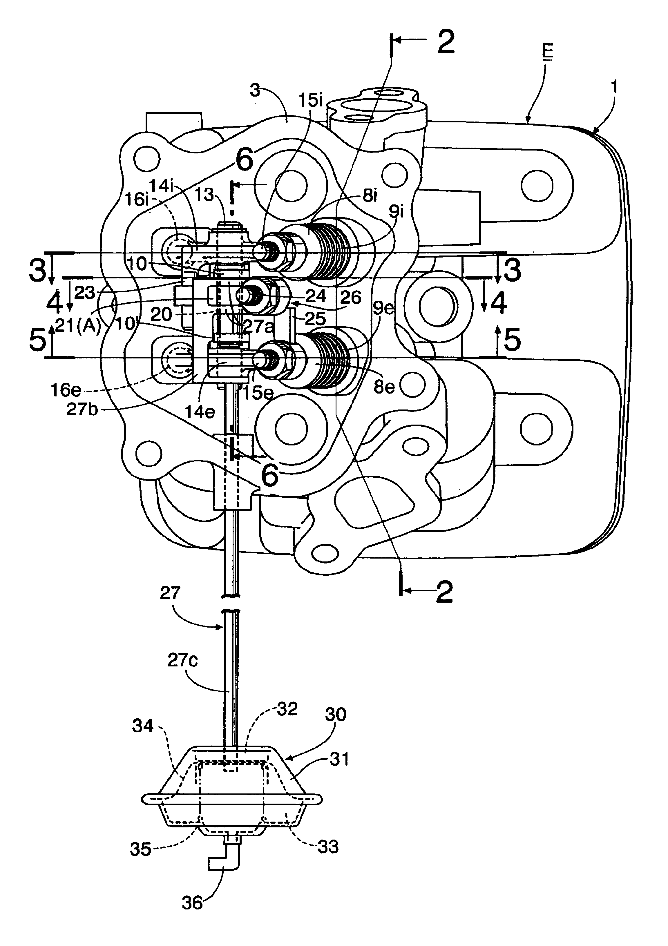
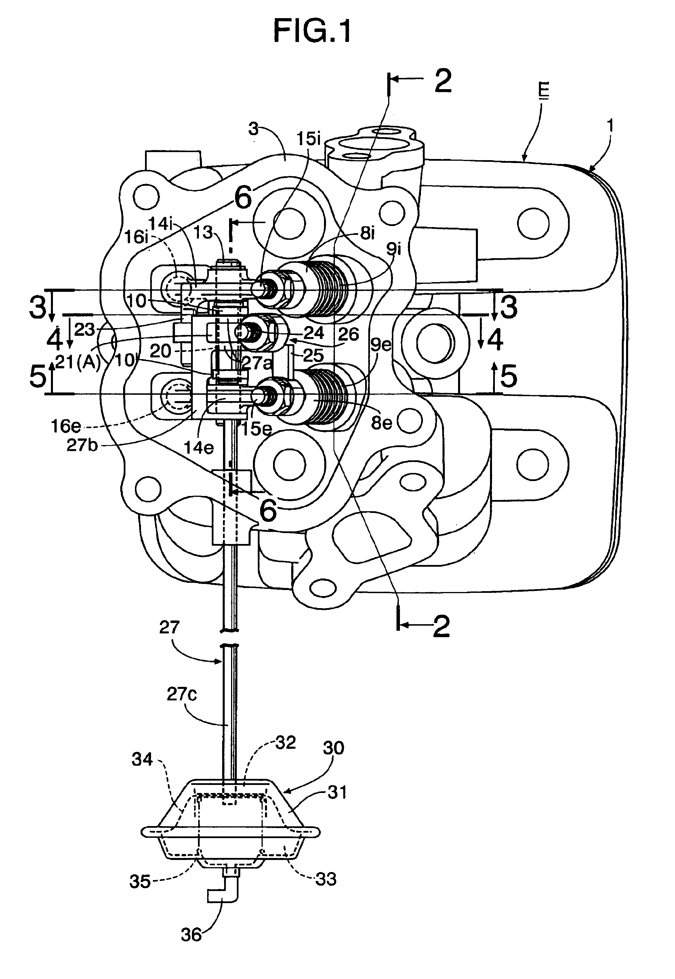
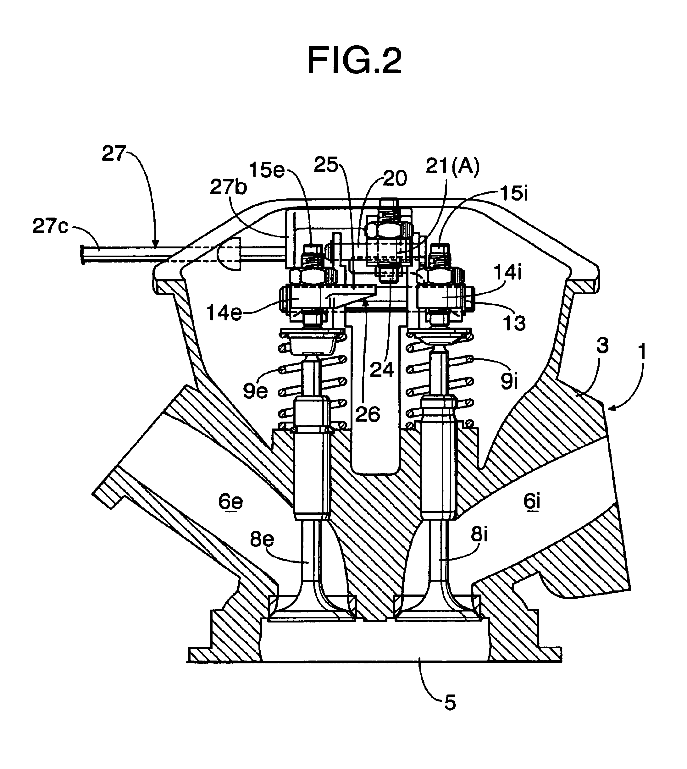
[0038]In FIGS. 1 to 6, an engine body 1 of an internal combustion engine E includes a cylinder block 2 having a cylinder bore 2a into which a piston 4 is fitted, and a cylinder head 3 joined to a top end of the cylinder block 2. The cylinder head 3 has a combustion chamber 5 communicating with the cylinder bore 2a, and an intake port 6i and an exhaust port 6e opening into a ceiling surface of the combustion chamber 5. A carburetor 7 (see FIG. 10) is connected to an upstream end of the intake port 6i. An exhaust muffler (not shown) is connected to a downstream end of the exhaust port 6e via an exhaust pipe.

[0039]An intake valve 8i and an exhaust valve 8e that open and close openings of the intake port 6i and the exhaust port 6e, respectively, into the combustion chamber 5 are mounted to the cylinder head 3 with their axes in parallel. Valve springs 9i and 9e that urge the intake valve 8i and the exhaust valve 8e in a...

second embodiment

[0055]Next, the invention shown in FIGS. 17 and 18 will be described

[0056]In the one-way connection means 26, the actuator 30 (see FIG. 1) controls movement of the auxiliary rocker arm 21 from the non-operating position A to an operation start point B1 and to an operation limit point B3. Specifically, the operating position B of the auxiliary rocker arm 21 is controlled within a range from the operation start point B1 via an operation middle point B2 to the operation limit point B3.

[0057]On the other hand, the connection piece 25 provided on the exhaust rocker arm 14e has a slope 25a always facing a tip end of the gap adjustment bolt 24 of the auxiliary rocker arm 21 regardless of the non-operating position A, the operation start point B1, the operation middle point B2 and the operation limit point B3 of the auxiliary rocker arm 21. The slope 25a descends toward the non-operating position A of the auxiliary rocker arm 21. The slope 25a causes a gap g between the gap adjustment bolt ...


PUM


Abstract

An exhaust gas reflux apparatus for an internal combustion engine includes one-way connection means provided between an intake rocker arm and an exhaust rocker arm. The one-way connection means moves between a non-operating position where the intake and exhaust rocker arms are released and an operating position where the intake and exhaust rocker arms are connected to open the exhaust valve only when the intake rocker arm rocks in a valve opening direction of the intake valve. An actuator for switching the one-way connection means between the non-operating position and the operating position is connected to the one-way connection means. Thus, an exhaust gas is sucked into a combustion chamber from an exhaust port using a general exhaust valve in an intake stroke, when exhaust gas reflux is required.

Description

BACKGROUND OF THE INVENTION[0001]1. Field of the Invention[0002]The present invention relates to an improvement in an exhaust gas reflux apparatus for an internal combustion engine that refluxes an exhaust gas into a combustion chamber to inhibit an excessive increase in combustion temperature of air-fuel mixture and to reduce NOx concentration in the exhaust gas.[0003]2. Description of the Related Art[0004]A known exhaust gas reflux apparatus for an internal combustion engine is, as disclosed in Japanese Utility Model Laid-Open No. 55-137245, such that an exhaust gas reflux valve is provided between a combustion chamber and an exhaust port, the exhaust gas reflux valve is opened in an interlocked manner with an intake rocker arm that is driven to open an intake valve, depending on operation conditions of the internal combustion engine, and an appropriate amount of exhaust gas is sucked into the combustion chamber from the exhaust port during an intake stroke.[0005]Such a constructi...

Claims


Application Information

Patent Timeline
IPC IPC(8): F01L1/00F01L1/46F01L1/18F01L1/14F01L13/00F02M25/07
CPCF01L1/146F01L1/181F01L1/46F01L13/0021F02M25/0747F02M25/0752F02M25/0774F02D13/0276Y02T10/18Y02T10/121F01L13/0036F01L2800/10F01L2820/034F02M26/55F02M26/41F02M26/01F01L2013/106F01L2305/00Y02T10/12
Inventor KASHIMA, SOUJIIKEDA, TOSHIMITSUKASAI, AKIHITO
Owner HONDA MOTOR CO LTD
Why Eureka
Try Eureka