System and method for x-ray fluoroscopic imaging

a fluoroscopic imaging and fluorescence technology, applied in the field of fluoroscopy, can solve the problems of obscuring glare and contrast loss, limited use of fluoroscopy at 30 video frames/second alone, and the inability to switch to a high detail mode, etc., to achieve accurate image, reduce or eliminate scattered radiation

Inactive Publication Date: 2005-05-17
UNIV OF MASSACHUSETTS MEDICAL CENT
View PDF47 Cites 273 Cited by
  • Summary
  • Abstract
  • Description
  • Claims
  • Application Information

AI Technical Summary

Benefits of technology

[0011]An image store used with the CCD controller allows manipulation of the CCD sensor output signals by a data processor. The system can also be adapted to operate at higher frame rates enabling the counting of x-ray events. This provides energy measurements of x-ray transmissions that are useful in certain applications. Preferred embodiments of the system may operate at variable speeds such as, without limitation, 3, 7.5, 15, 30, 60 and 90 frames per second.
[0013]In preferred embodiments, the spatial resolution of the detectors may range between 0.2 line pair per mm or cycle / mm to 15 cycles per mm to accurately image the anatomical features or medical devices used in conjunction with the organs or anatomical features.

Problems solved by technology

However, fluoroscopy at 30 video frames / second alone is of limited use without the capability of switching to a high detail mode.
In spite of the technical improvements, this technology suffers from several inherent limitations.
Veiling glare and contrast loss is one of the more typical problems inherent in the electro-optic design of the image intensifier.
Shielding of image intensifiers with “mu-metal” is essential but in many cases a significant amount of S-type distortion is still present.
This distortion is not only bothersome during treatment procedures requiring high spatial accuracy, but also changes spatially as the intensifier is moved, making it difficult to correct mathematically.
Other types of distortion such as pincushion and barrel type distortions are caused by the inherent limitations of the electron focusing optics.
Pincushion and barrel distortions are tolerable in many instances but they present a hindrance in the proper visualization of anatomy.
In addition, the gain of image intensifiers is known to degrade with time due in part to out-gassing of components in the vacuum chamber and degradation of the photocathode.
Also, the relatively large size of image intensifiers may be problematic in biplanar installations.
Even in simple fluoroscopic installations the camera tower frequently interferes with the overhead radiographic x-ray tube and other structures.
However, radiation exposure to patients during diagnostic and interventional cardiac procedures has increased as a result of the increased complexity of the angiographic procedures performed in current clinical practice.
The rapid proliferation of these procedures has resulted in a small but alarming number of non-stochastic radiation effects on patients.

Method used


Image

  • System and method for x-ray fluoroscopic imaging
  • System and method for x-ray fluoroscopic imaging
  • System and method for x-ray fluoroscopic imaging

Examples


Embodiment Construction

[0098]Systems for quantitative radiographic imaging are described in U.S. Pat. No. 5,864,146 issued on Jan. 26, 1999 to Karellas and in WO 97 / 42877 published on Nov. 20, 1997 also by Karellas, both of which being incorporated herein by reference in their entirety.

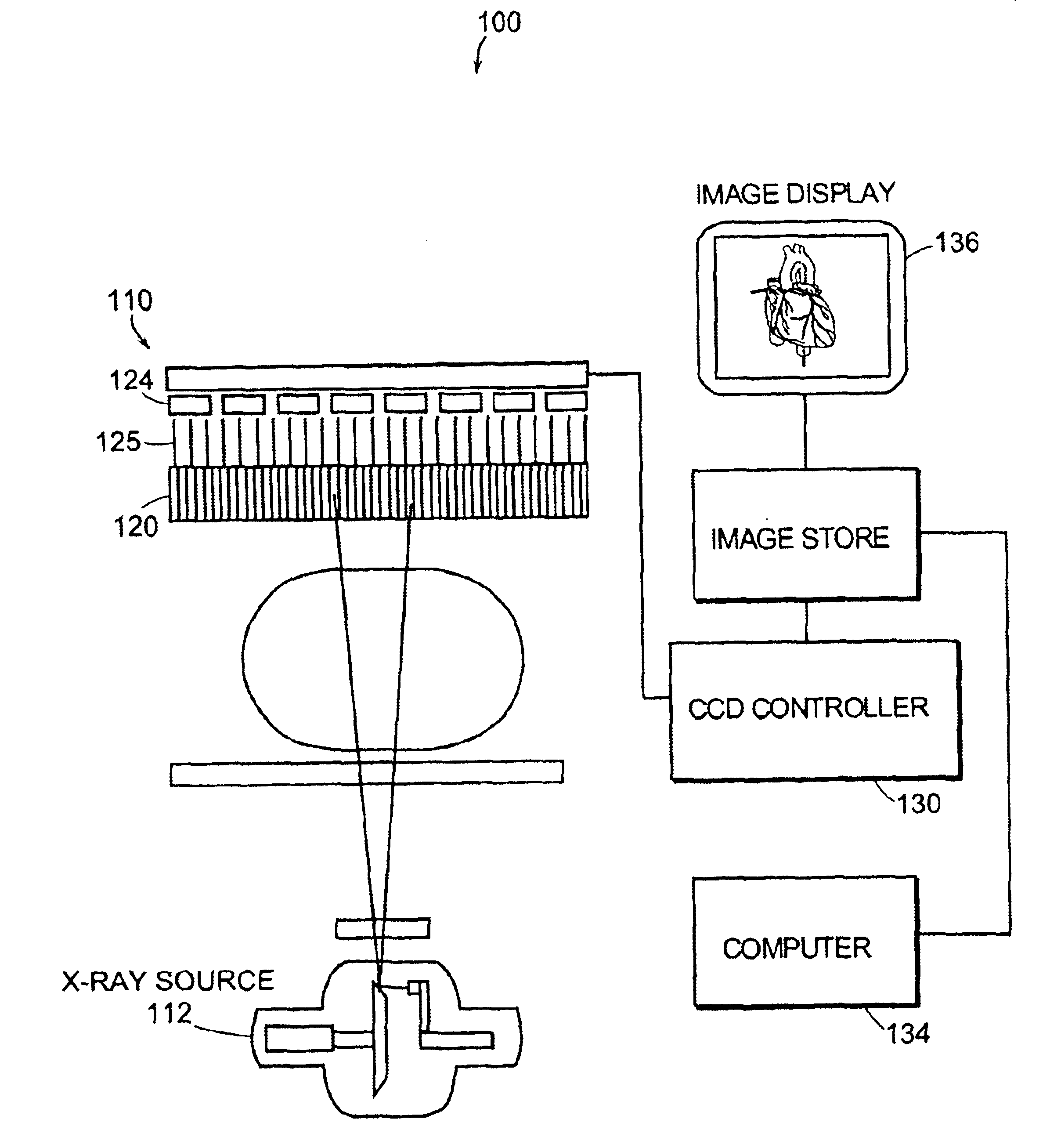
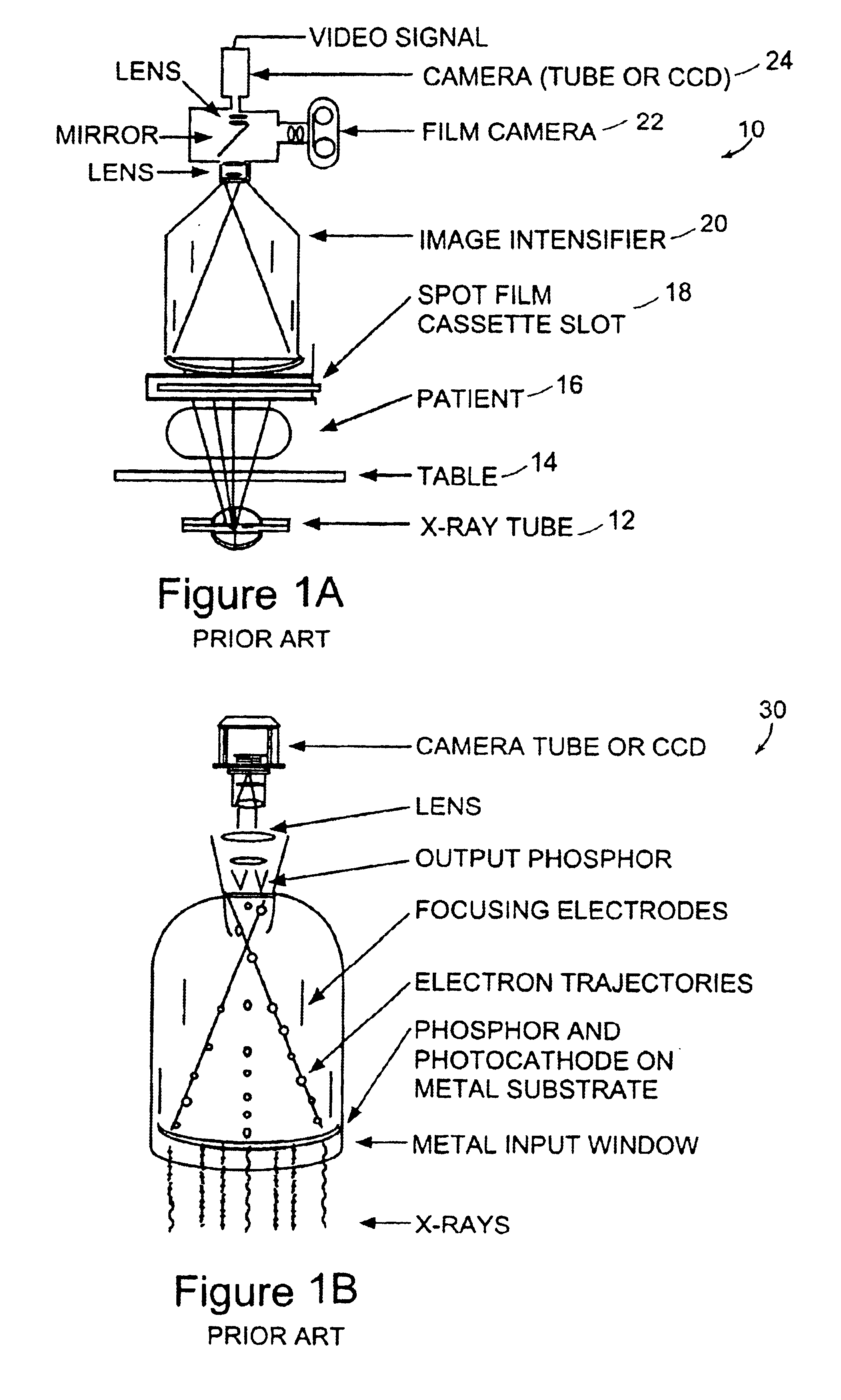
[0099]FIGS. 1A and 1B illustrate prior art fluoroscopic imaging devices for interventional radiology and cardiovascular applications which have traditionally used image intensifiers 20 coupled to either charge-coupled devices (CCDs) 24 or pick-up tubes. Conventionally, x-ray image intensifiers are used in conjunction with television cameras 24 for fluoroscopy. The x-ray image intensifier 20 detects the x-ray image and converts it to a small, bright image of visible light. Tropically, this visible image is then transferred by lenses to a television camera for final display on a monitor. FIG. 1B illustrates the details of the detection and amplification process.

[0100]While such devices provide image quality sufficient for mos...


PUM


Abstract

A system for x-ray fluoroscopic imaging of bodily tissue in which a scintillation screen and a charge coupled device (CCD) is used to accurately image selected tissue. An x-ray source generates x-rays which pass through a region of a subject's body, forming an x-ray image which reaches the scintillation screen. The scintillation screen re-radiates a spatial intensity pattern corresponding to the image, the pattern being detected by the CCD sensor. In a preferred embodiment the imager uses four 8×8-cm three-side buttable CCDs coupled to a CsI:T1 scintillator by straight (non-tapering) fiberoptics and tiled to achieve a field of view (FOV) of 16×16-cm at the image plane. Larger FOVs can be achieved by tiling more CCDs in a similar manner. The imaging system can be operated in a plurality of pixel pitch modes such as 78, 156 or 234-μm pixel pitch modes. The CCD sensor may also provide multi-resolution imaging. The image is digitized by the sensor and processed by a controller before being stored as an electronic image. Other preferred embodiments may include each image being directed on flat panel imagers made from but not limited to, amorphous silicon and / or amorphous selenium to generate individual electronic representations of the separate images used for diagnostic or therapeutic applications.

Description

GOVERNMENT SUPPORT[0001]The invention was supported, in whole or in part, by a Grant No. R01 HL65551 from the National Institutes For Health. The Government has certain rights in the invention.BACKGROUND OF THE INVENTION[0002]The term fluoroscopy refers to the use of x-ray imaging techniques for real-time visualization of internal anatomy and function for diagnostic and therapeutic purposes. Physiologic functions such as peristalsis and flow, and real-time image feedback for placement of devices, such as catheters or intravascular stents are typical examples of fluoroscopic imaging. However, fluoroscopy at 30 video frames / second alone is of limited use without the capability of switching to a high detail mode. This mode may be activated by a command to produce a spot image ‘snapshot’ and in many applications acquisition of rapid sequences of spot images or high detail images at a higher radiation dose are essential. In this mode, the system operates in a rapid sequence radiographic ...

Claims


Application Information

Patent Timeline
Patent Type & Authority Patents(United States)
IPC IPC(8): A61B6/00H01L27/148H01L31/0232
CPCA61B6/481A61B6/482H01L31/02322H01L27/14831A61B6/504H04N5/32
Inventor KARELLAS, ANDREWVEDANTHAM, SRINIVASANSURYANARAYANAN, SANKARARAMAN
Owner UNIV OF MASSACHUSETTS MEDICAL CENT
Why Eureka
Try Eureka