Optical add-drop multiplexer

a multiplexer and optical technology, applied in multiplex communication, transmission monitoring, instruments, etc., can solve the problems of degrading the s/n ratio, output saturation, receiving sensitivity degrading, etc., and achieve the effect of reducing the cost and size of the oadm nod

Inactive Publication Date: 2005-05-17
RAKUTEN GRP INC
View PDF35 Cites 9 Cited by
  • Summary
  • Abstract
  • Description
  • Claims
  • Application Information

AI Technical Summary

Benefits of technology

[0014]An object of the present invention is to provide an OADM capable of dropping / adding a signal light having arbitrary wavelength within a node and to reduce cost and size of the OADM node by defining a fault detection signal of an optical signal cut-off in a wavelength / space multiplexing oriented optical layer which does not conflict with a transmitter of SONET / SDH or other framing format.

Problems solved by technology

However, when gain of such semiconductor optical amplifier is small, S / N ratio is degraded due to spontaneously emitted light noise when a signal light is input to the optical amplifier.
However, since, when an output of the semiconductor optical amplifier is increased, inverted population density of carrier is reduced, gain is saturated, resulting in an output saturation.
Under the condition of such output saturation, the signal waveform is distorted, causing receiving sensitivity to be degraded.
Further, since, when such semiconductor optical switch is moduled, optical coupling loss of a semiconductor chip and optical fiber is several dB, the saturated output power becomes small.
Since a practical difference between output power limit and S / N degradation is as narrow as several dB, the freedom of design of optical level in constructing a system is substantially restricted.
Under such conditions, a severe optical level regulation is necessary, so that the number of monitor items for light intensity is increased, which restricts the reduction of scale of a node.

Method used


Image

  • Optical add-drop multiplexer
  • Optical add-drop multiplexer
  • Optical add-drop multiplexer

Examples


first embodiment

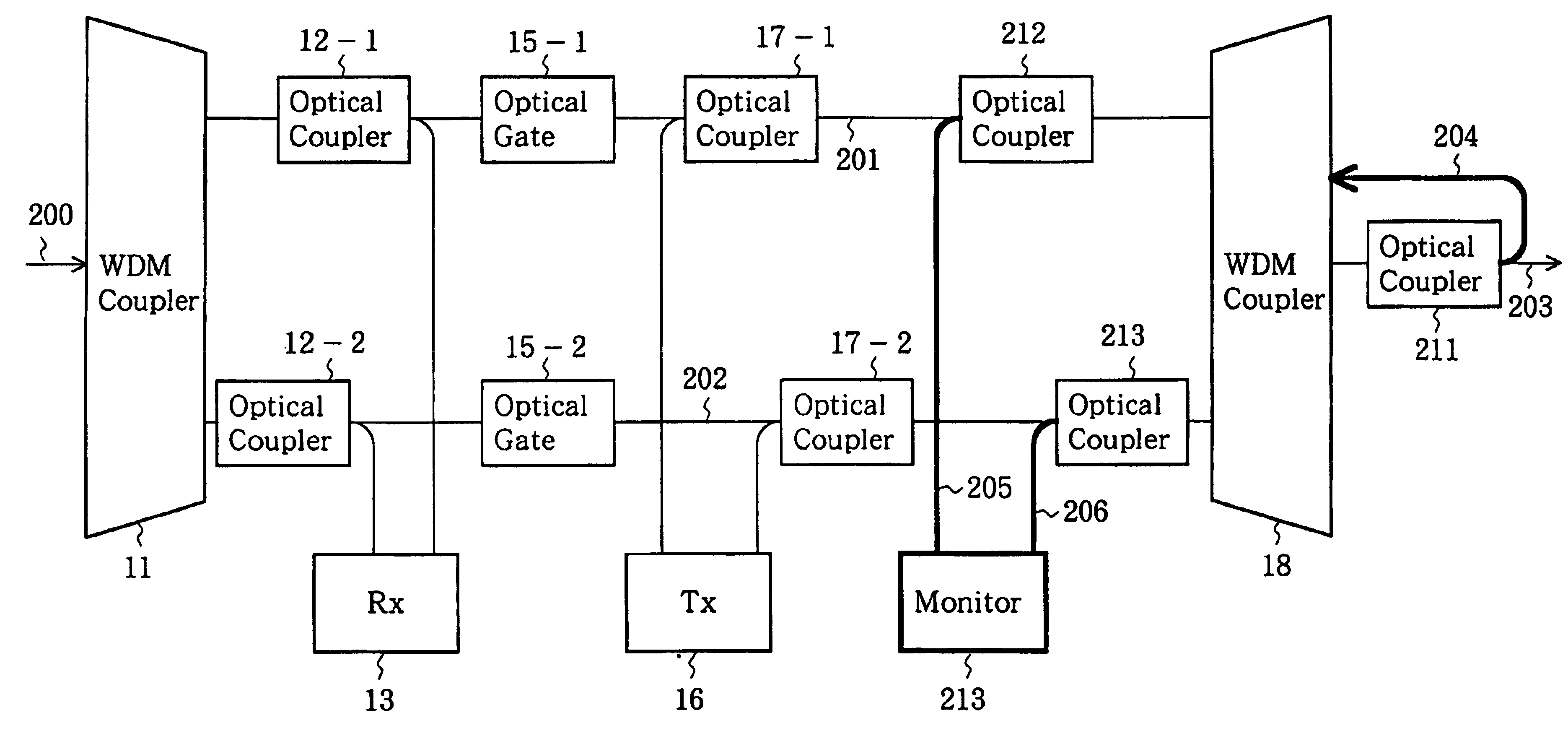
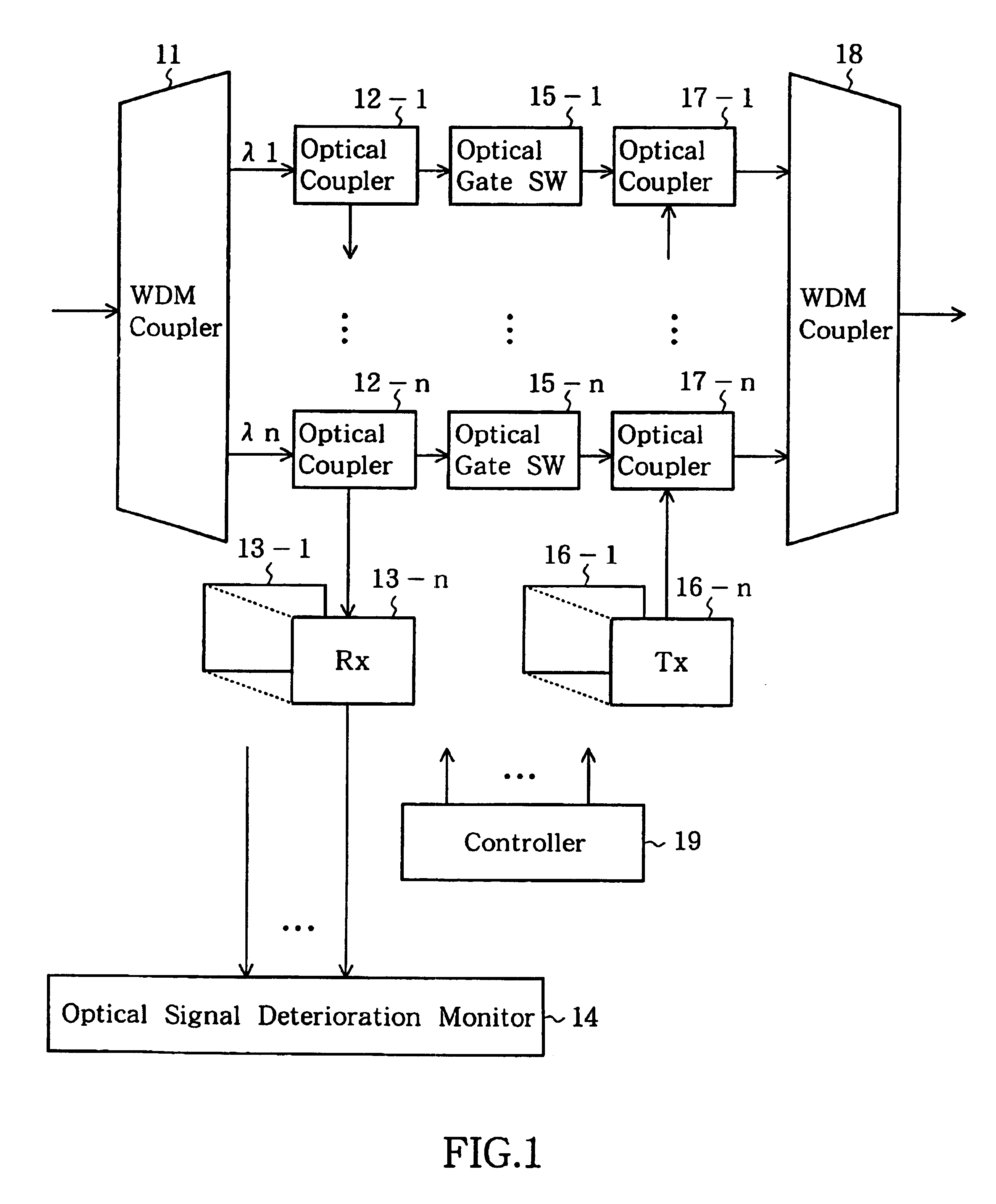
[0082]An OADM shown in FIG. 1 constitutes a node in a network and, in order to drop (branch) / add (insert) wavelength light signals of a wavelength-multiplexed light in this node, respectively, includes an optical wavelength division coupler 11 for wavelength-dividing a wavelength-multiplexed light to wavelength lights having different wavelengths, optical couplers 12-1 to 12-n, light receivers 13-1 to 13-n, an optical signal deterioration monitor 14, optical gate switches 15-1 to 15-n, light transmitters 16-1 to 16-n, optical couplers 17-1 to 17-n, a controller 19 and an optical wavelength multiplex coupler 18 for wavelength-multiplexing lights having different wavelengths. The optical wavelength division coupler 11 and the optical wavelength multiplex coupler 18 are constituted by using array waveguide diffraction gratings, respectively. The optical couplers 12-1 to 12-n, the light receivers 13-1 to 13-n, the optical gate switches 15-1 to 15 n, the light transmitters 16-1 to 16-n ...

second embodiment

[0092]the present invention will be described with reference to FIG. 3 The OADM of this embodiment is constructed with an optical WDM coupler 21, optical couplers 22-1 to 22-n bi-directionally connected to the optical WDM coupler 21, light receivers 23-1 to 23-n connected to outputs of the respective optical couplers 22-1 to 22-n, light transmitters 24-1 to 24-n, optical couplers 25-1 to 25-n bi directionally connected to the respective optical couplers 22-1 to 22-n and receiving outputs of the respective light transmitters 24-1 to 24-n, optical gate switches 26-1 to 26-n bi-directionally y connected to the respective optical couplers 25-1 to 25-n, reflection mirrors 27-1 to 27 n bi-directionally connected to the respective optical couplers 26-1 to 26-n, a circulator 28 and a controller 29.

[0093]The second embodiment differs from the first embodiment in that the wavelength-multiplexed input light is input through the circulator 28 to the optical WDM coupler 21, that signal lights ha...

third embodiment

[0095]In a case where the OADM allows a signal light having wavelength λ1 to pass, the signal light is derived by the optical WDM coupler 21 and, after passed through the optical couplers 22-1 and 25-1 and the optical gate switch 26-1, reflected by the reflection mirror 27-1. The signal light reflected by the reflection mirror 27-1 passes through the optical gate switch 26-1 and the optical couplers 25-1 and 22-1 to the optical WDM coupler 21 and is output from the optical circulator 28. When the signal having wavelength λ1 is to be dropped or added, the optical gate switch 26-1 is turned off under control of the controller 29 to cut the passage between the optical coupler 25-1 and the reflection mirror 27-1 and to input the signal light having wavelength λ1 from the light transmitter 24-1 to the optical WDM coupler 21 through the optical couplers 25-1 and 22-1. This is the same for signal lights of other wavelengths λ2 to λn. The light which is obtained by the wavelength multiplexi...


PUM


Abstract

An optical wavelength division coupler 11 wavelength-divides a wavelength multiplexed light to respective wavelength lights each of which is dropped to an optical gate switch 15-i (i=1˜n) and a light receiver 13-i by an optical coupler 12-i and supplied to an optical light fault monitor 14 through the light receiver 13-i. When the optical signal deterioration monitor 14 detects an optical loss of wavelength (OLOW), an optical loss of signal (OLOS) or an optical signal degrade (OSD) in wavelength lights processed by the optical coupler 12-i as a fault detection signal in an optical layer, a controller 19 controls the optical gate switch 15-i to cut off wavelength light passing therethrough and sends an optical alarm indication signal (AIS-O) to a downstream side. Therefore, when a loss of signal is detected by the light receiver 13-i, the optical signal deterioration monitor 14 can know the alarm indication signal (AIS) from the upstream side, removing the necessity of special hardware therefor.

Description

[0001]This application is a division of the application No. 09 / 123,529 filed on Jul. 28, 1998, now U.S. Pat. No. 6,404,525.BACKGROUND OF THE INVENTION[0002]The present invention claims priorities from Japanese Patent Applications No.9-205706 filed Jul. 31, 1997, No. 9-210562 filed Aug. 5, 1997 and No. 9-273268 filed Sep. 22, 1997, which are incorporated herein by reference.[0003]1. Field of the Invention[0004]The present invention relates to an Optical Add-Drop Multiplexer (OADM) capable of switching a transmission line of a wavelength-multiplexed optical signal without electrically terminating the optical signal and an optical signal monitor utilizing the OADM.[0005]2. Description of the Related Art[0006]As the optical network, a network constructed on the basis of SONET (Synchronous Optical Network) / SDH (Synchronous Digital Hierarchy) using the time division multiplexing (TDM) has been used popularly. In a network based on this SONET / SDH, the switching of transmission line is usua...

Claims


Application Information

Patent Timeline
Patent Type & Authority Patents(United States)
IPC IPC(8): H04J14/02H04B10/08H04B10/02
CPCH04B10/03H04B10/0771H04J14/0212H04J14/0245H04J14/0283H04J14/0287H04J14/0293H04J14/0249H04J14/0241H04J14/0227H04B2210/071H04B2210/072H04J14/0216H04J14/0278
Inventor SHIMOMURA, HIROFUMIHENMI, NAOYATAKESHITA, HITOSHI
Owner RAKUTEN GRP INC
Why Eureka
Try Eureka