Method of fabricating semiconductor device and system of fabricating semiconductor device

Active Publication Date: 2005-05-24
SANYO ELECTRIC CO LTD
View PDF11 Cites 13 Cited by
  • Summary
  • Abstract
  • Description
  • Claims
  • Application Information

AI Technical Summary

Benefits of technology

[0035]In this case, the laser oscillator preferably includes a first mirror transmitting about half of the oscillated laser beam while reflecting about the remaining half of the oscillated laser beam and a second mirror reflecting the laser beam reflected by the first mirror, the laser beam transmitted through the first mirror is preferably incident upon the first optical fiber member, and the laser beam reflected by the second mirror is preferably incident upon the second optical fiber member. According to this structure, laser beams of about half in intensity are simultaneously incident upon the first and second optical fiber members respectively, whereby a linear (rectangular) laser beam having a large longitudinal length can be easily obtained.
[0036]In the aforementioned method of fabricating a semiconductor device according to the first aspect, the optical fiber member preferably includes a first optical fiber member and a second opt

Problems solved by technology

In the aforementioned conventional excimer laser annealing (ELA), however, the absorptivity is remarkably influenced by the thickness or the quality of the heated semiconductor layer and the beam intensity is dispersed due to instability of pulse oscillation, and hence it is difficult to homogeneously heat the semiconductor layer.
Therefore, device characteristics are inconveniently dispersed to reduce the yield.
Further, the conventional ELA inconveniently results in a high device cost or a high operation cost.
In addition, it is difficult to perform high-speed scanning with the laser beam due to the pulse oscillation.
Thus, the throughput (productivity) is disadvantageously reduced.
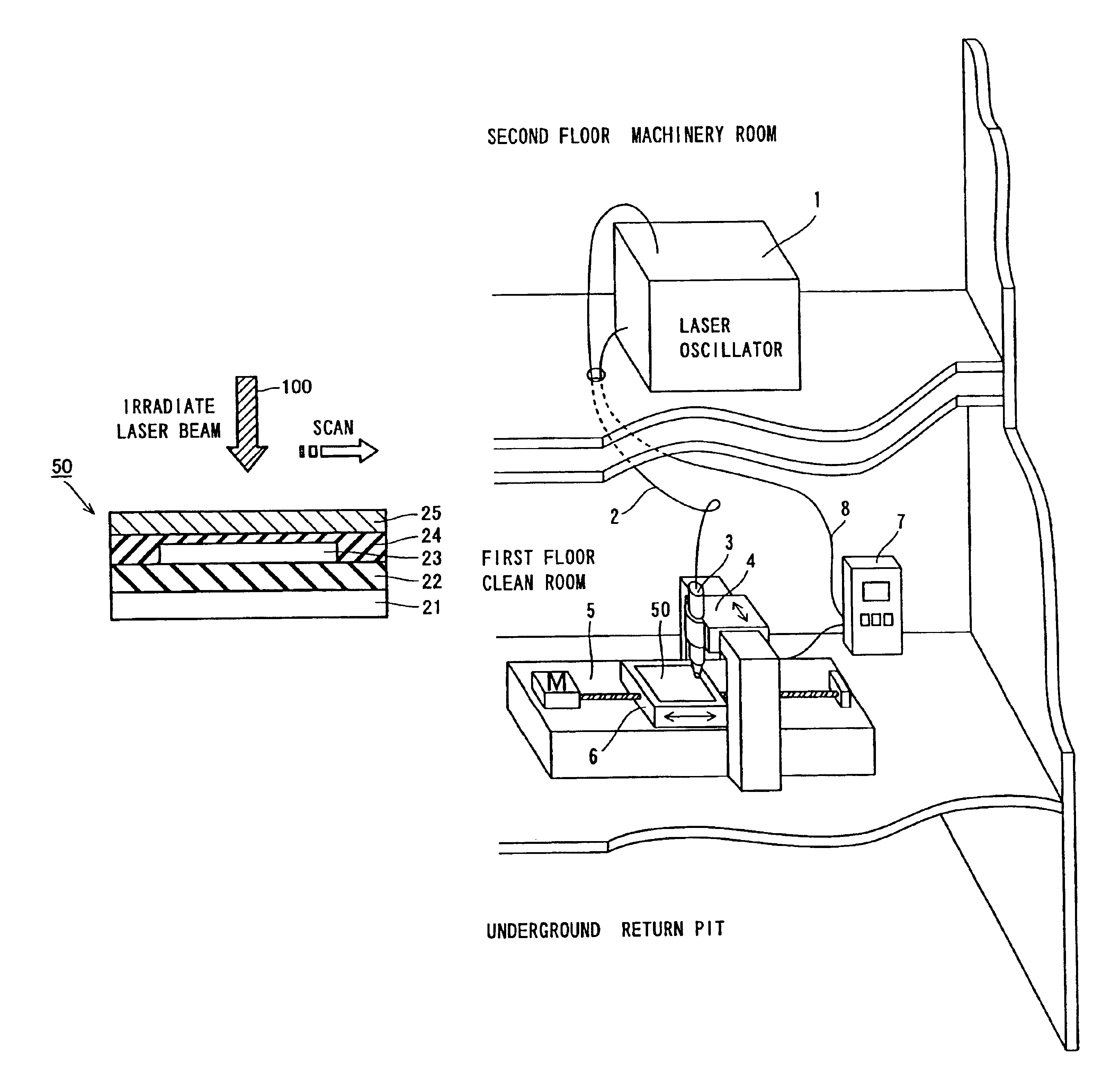
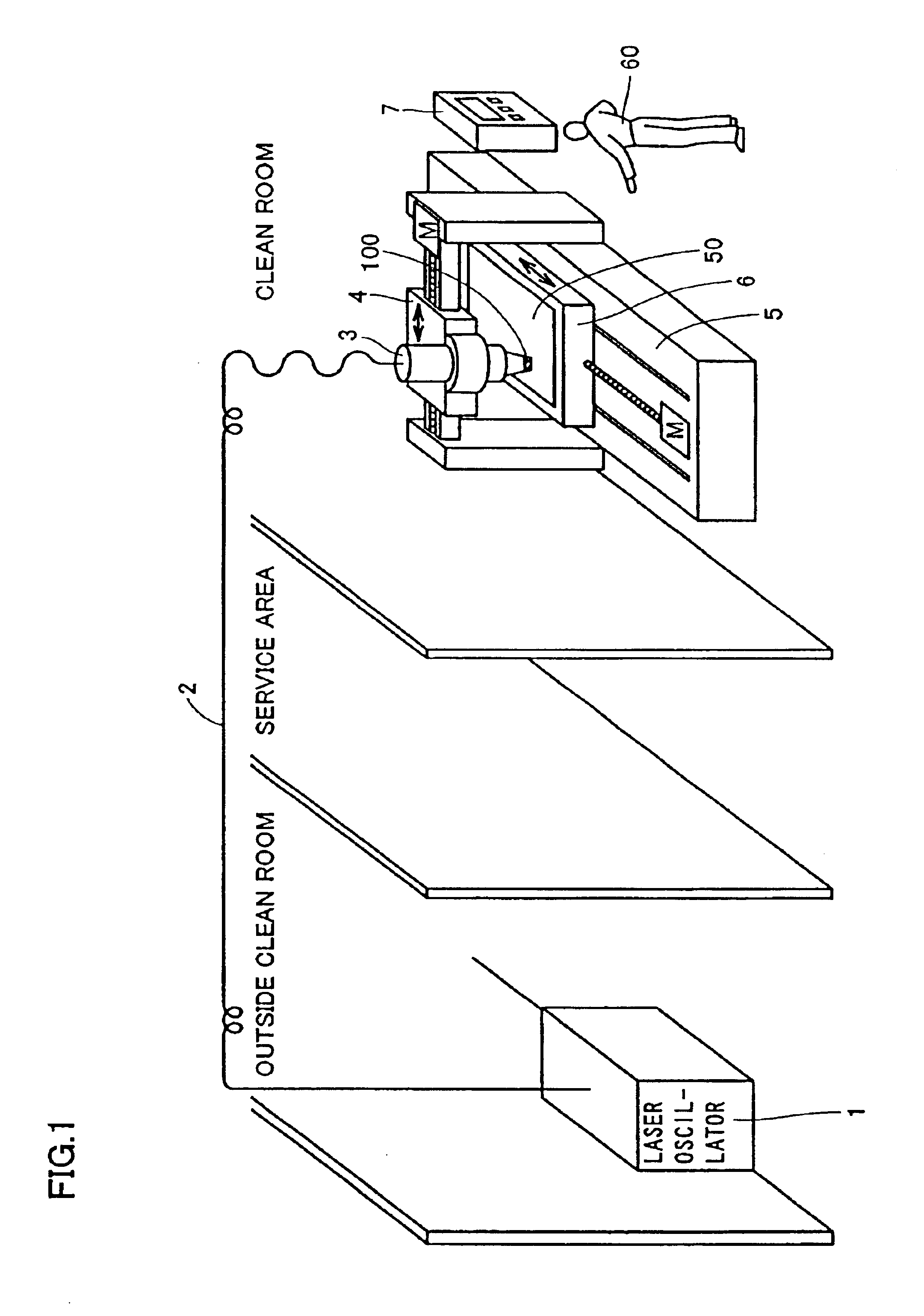
In the aforementioned conventional method employing a YAG laser beam, however, a laser oscillator and an irradiation optical system are connected with each other through an optical system including a mirror, a lens or the like, leading to difficulty in miniaturizing the overall optical system including the irradiation optical system.
Further, all of the laser oscillator, the irradiation optical system and the optical system for connecting the laser oscillator and the irradiation optical system with each other must be installed in a clean room (dust-free room), and hence the size of the clean room is inconveniently increased.
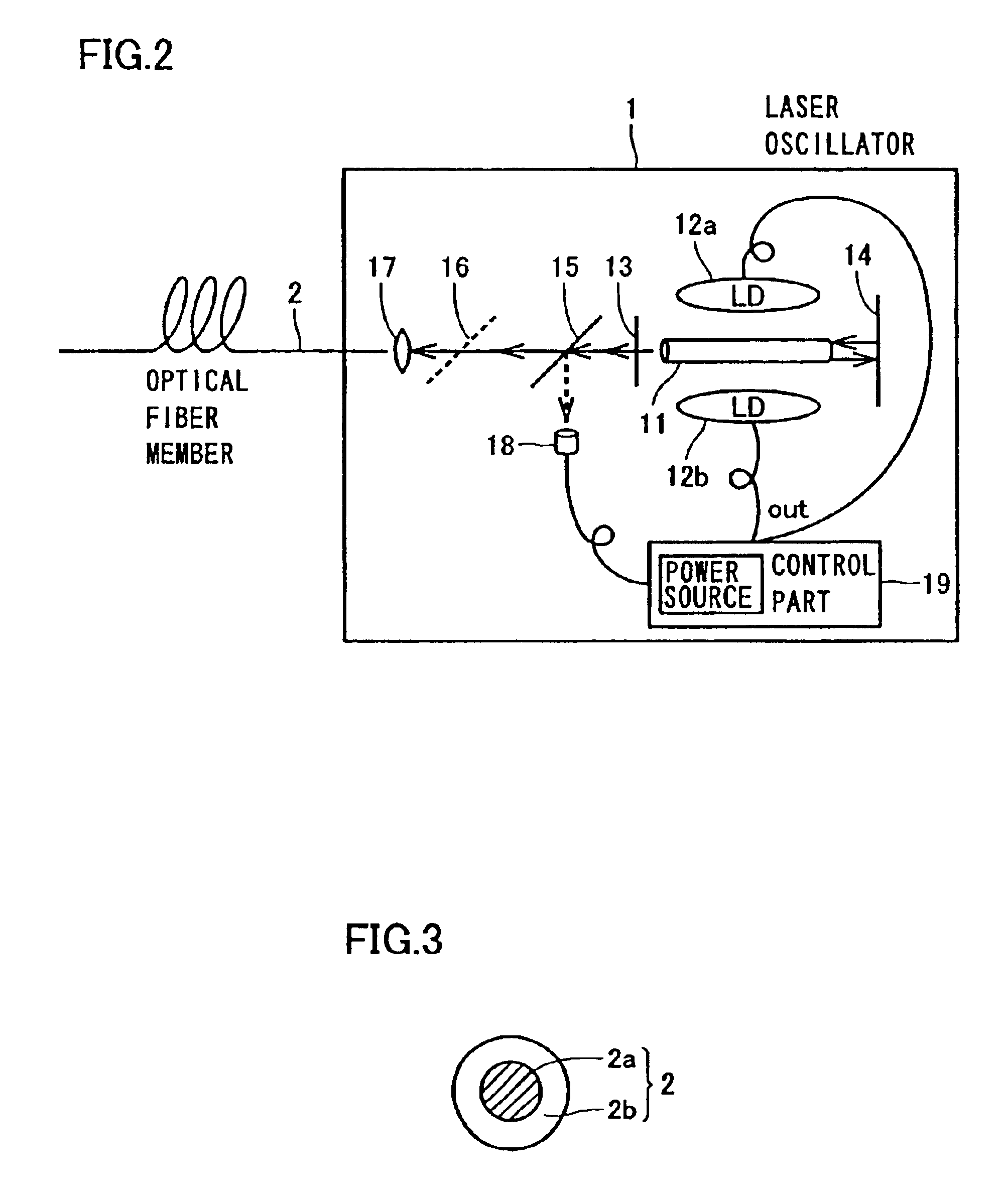
In the aforementioned method employing the optical fiber bundle formed by bundling a plurality of optical fiber members, however, it is so difficult to introduce a laser beam condensed by

Method used


Image

  • Method of fabricating semiconductor device and system of fabricating semiconductor device
  • Method of fabricating semiconductor device and system of fabricating semiconductor device
  • Method of fabricating semiconductor device and system of fabricating semiconductor device

Examples


Embodiment Construction

[0054]An embodiment of the present invention is now described with reference to the drawings.

[0055]First, the structure of a laser irradiator employed for a method of fabricating a semiconductor device and a system of fabricating a semiconductor device according to this embodiment is described with reference to FIGS. 1 to 3. This laser irradiator comprises a laser oscillator 1, an optical fiber member 2, an irradiation optical system 3, an irradiation optical system moving part 4, a base 5, a heater plate 6 and a control panel 7. A substrate 50 is set on the heater plate 6.

[0056]The optical fiber member 2 connects the laser oscillator 1 and the irradiation optical system 3 with each other. The laser oscillator 1 is installed in a room outside a clean room (dust-free room), while the irradiation optical system 3, the irradiation optical system moving part 4, the base 5, the heater plate 6 and the control panel 7 are installed in the clean room. A service area having intermediate clea...


PUM

PropertyMeasurementUnit
Diameteraaaaaaaaaa
Lengthaaaaaaaaaa
Lengthaaaaaaaaaa

Abstract

A method of fabricating a semiconductor device capable of obtaining a high-density laser beam necessary for crystallizing a semiconductor layer or activating an impurity while miniaturizing a lens group provided on the outlet of an optical fiber member is provided. This method of fabricating a semiconductor device comprises steps of connecting a laser oscillator oscillating a near infrared laser beam and an irradiation optical system with each other through an optical fiber member having a single core part and heating a semiconductor layer by irradiating the near infrared laser beam from the irradiation optical system.

Description

BACKGROUND OF THE INVENTION[0001]1. Field of the Invention[0002]The present invention relates to a method of fabricating a semiconductor device and a system of fabricating a semiconductor device, and more particularly, it relates to a method of fabricating a semiconductor device including a step of heating a semiconductor layer with a laser beam and a system of fabricating a semiconductor device.[0003]2. Description of the Background Art[0004]A thin-film transistor (hereinafter referred to as a polycrystalline silicon TFT) employing a polycrystalline silicon film as an active layer has recently been employed as a pixel driving transistor for a liquid crystal display. In such a liquid crystal display, the performance of the polycrystalline silicon TFT must be improved in order to reduce the cost, improve the performance and render the display lightweight and compact. In order to improve the performance of the polycrystalline silicon TFT, a polycrystalline silicon film formed on a sub...

Claims


Application Information

Patent Timeline
IPC IPC(8): B23K26/00H01L21/265H01L21/00H01L21/02H01L21/336H01L21/20H01L21/301H01L21/26H01L21/268H01L21/70H01L29/66H01L29/786H01L21/324H01L21/78B23K26/12
CPCB23K26/0639B23K26/0643B23K26/0648B23K26/127B23K26/12B23K26/123H01L21/2026B23K26/0665B23K26/064H01L21/02683H01L21/02502H01L21/02678H01L21/02488H01L21/02422H01L21/02532H01L21/02598H01L21/02691H01L21/268
Inventor SOTANI, NAOYAHASEGAWA, ISAO
Owner SANYO ELECTRIC CO LTD
Why Eureka
Try Eureka