Aperture Coupled Cavity Backed Patch Antenna

a cavity-backed patch antenna and cavity-back technology, applied in the direction of individual energised antenna arrays, resonant antennas, antenna earthings, etc., can solve the problems of many antenna designers, the requirement is counterproductive to antenna design, and the conventional antenna system is confined within predefined limits, so as to reduce pim, facilitate the manufacturing of cavity, and reduce the effect of passive intermodulation

Inactive Publication Date: 2005-05-24
ANDREW CORP
View PDF15 Cites 34 Cited by
  • Summary
  • Abstract
  • Description
  • Claims
  • Application Information

AI Technical Summary

Benefits of technology

[0011]The cavity disposed between the printed circuit board and the ground plane of the antenna system can function electrically as a closed boundary when mechanically, the cavity has open corners. The open corner design facilitates ease in manufacturing the cavity. The open corners of the cavity can also have dimensions that permit resonance while substantially reducing Passive Intermodulation (PIM).
[0012]PIM can be further reduced by planar fasteners used to attach respective flanges and a planar center of a respective cavity to the ground plane of the printed circuit board and the ground plane of the antenna system. The planar fasteners can comprise a dielectric adhesive. In addition to the dielectric adhesive, the present invention can also employ other types of fasteners that reduce the use of dissimilar materials, ferrous materials, metal to metal contacts, deformed or soldered junctions and other similar materials in order to reduce PIM.
[0013]For example, the patch radiators can be spaced apart by plastic fasteners that permanently “snap” into pl...

Problems solved by technology

Requiring antenna designers to build an antenna to fit within a radome as opposed to designing or sizing a radome after an antenna is constructed creates many problems for antenna designers.
Such a requirement is counterproductive to antenna design since antenna designers recognize that the size of antennas are typically a function of their operating frequency.
Conventional antenna systems confined within predefined volumes, such as radomes, usually cannot provide for large beamwidths in addition to large bandwidths.
In other words, the conventional art typically requires costly and bulky hardware in order to prov...

Method used


Image

  • Aperture Coupled Cavity Backed Patch Antenna
  • Aperture Coupled Cavity Backed Patch Antenna
  • Aperture Coupled Cavity Backed Patch Antenna

Examples


Embodiment Construction

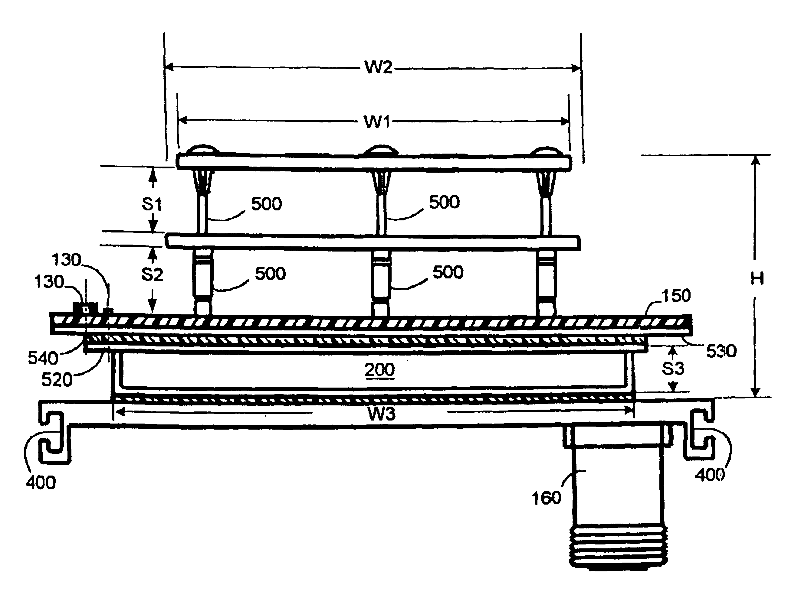
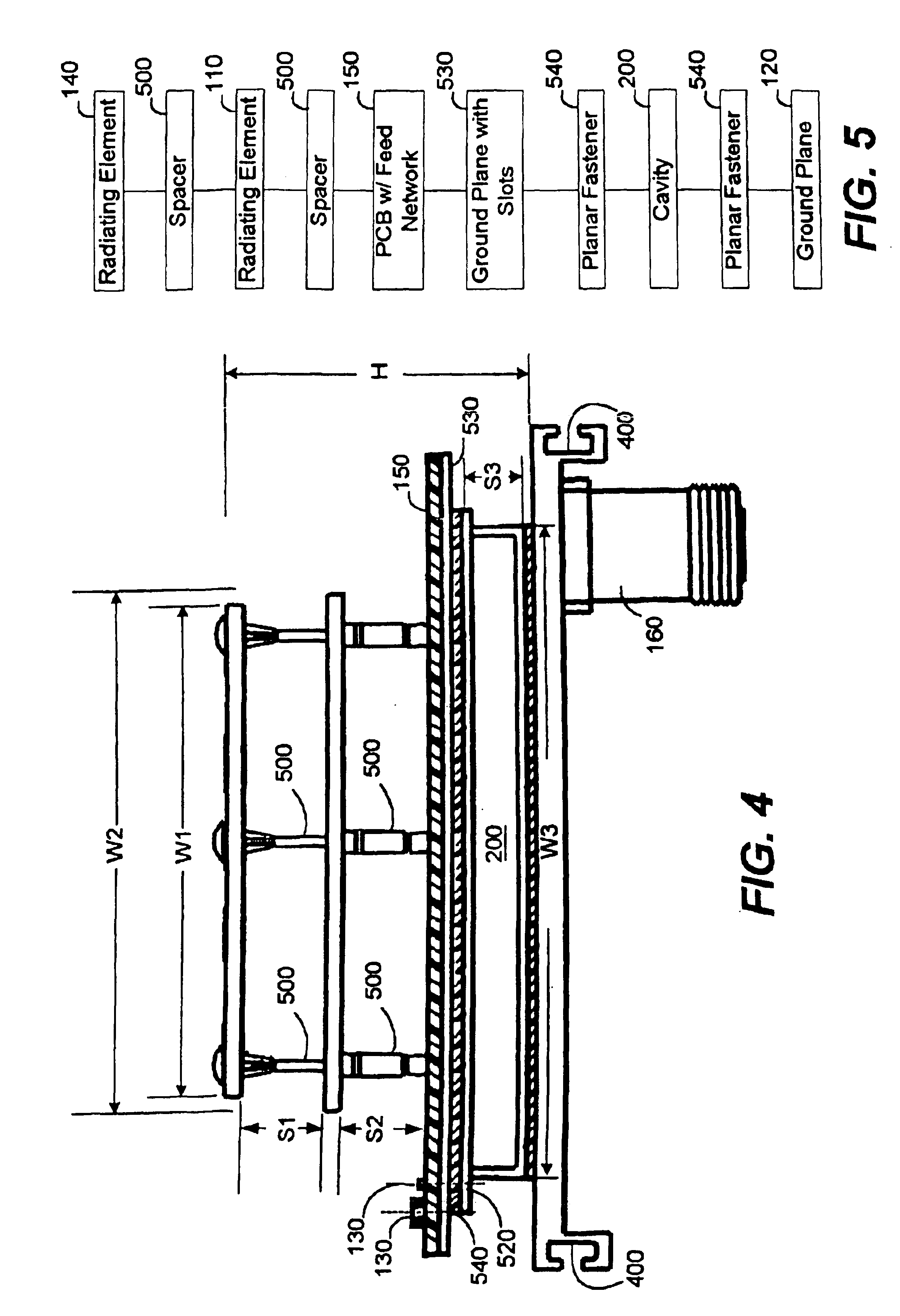
[0033]The antenna of the present invention can solve the aforementioned problems and is useful for wireless communications applications, such as personal communication services (PCS) and cellular mobile radio telephone (CMR) service. The antenna system can include one or more patch radiators, a printed circuit board disposed adjacent to the one or more patch radiators, and plurality of slots disposed within a ground plane of the printed circuit board. The antenna further includes a cavity disposed adjacent to the ground plane of the printed circuit board and a second ground plane disposed adjacent to the cavity. The antenna system radiates RF energy with relatively wide beamwidth and bandwidth.

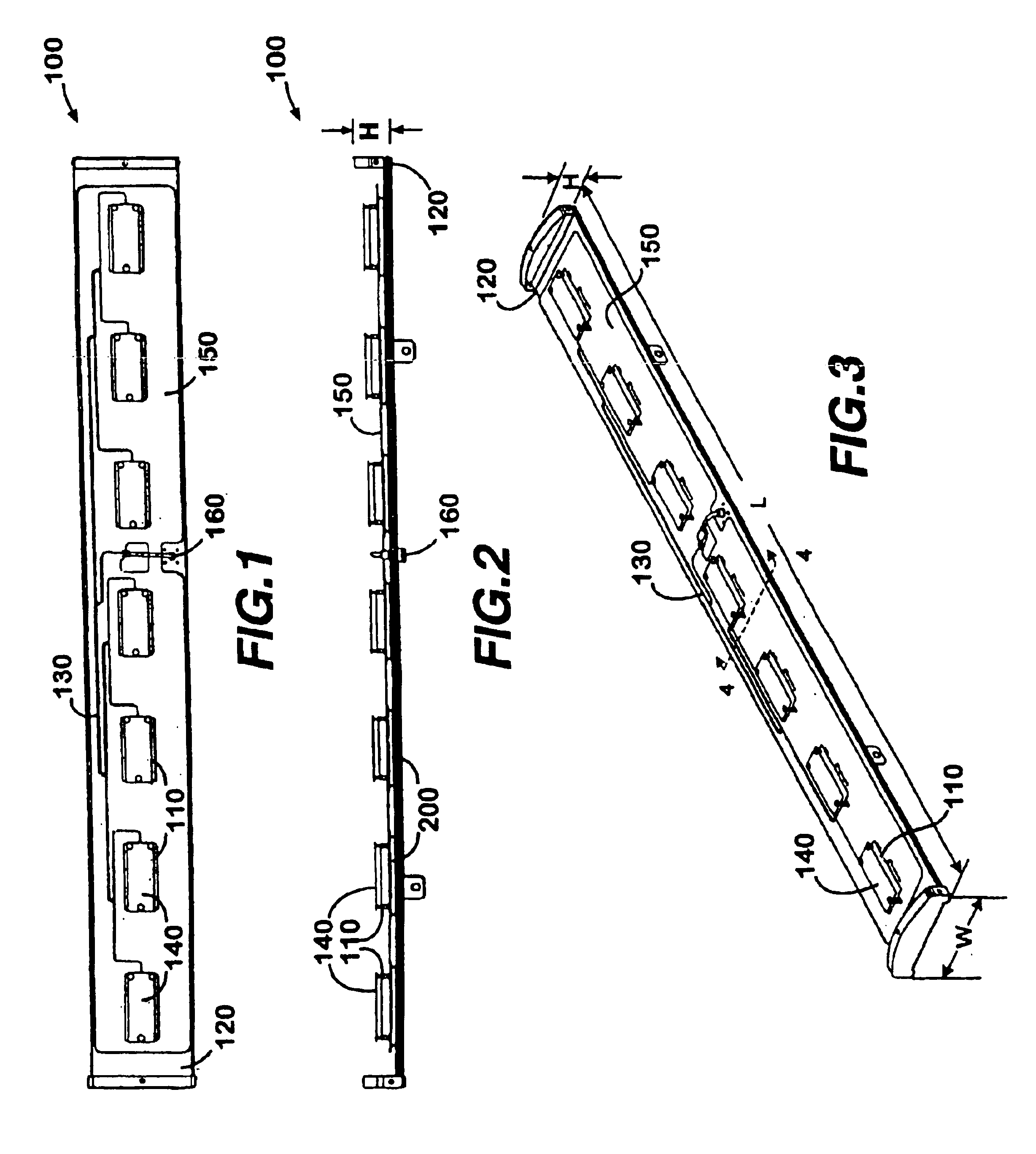
[0034]Turning now to the drawings, in which like reference numerals refer to like elements, FIG. 1 is an illustration showing an elevational view of one exemplary embodiment of the present invention. Referring now to FIG. 1, an antenna system 100 is shown for communicating electromagnetic sign...


PUM


Abstract

A compact antenna system can generate RF radiation fields having increased beamwidths and bandwidths. The antenna system can include one or more patch radiators. The lower patch radiators can be mounted to a printed circuit board that can include a ground plane which defines a plurality of slots. The slots within the ground plane of the printed circuit board can be excited by stubs that are part of the feed network of the printed circuit board. The slots, in turn, can establish RF radiation in a cavity which is disposed adjacent to the ground plane of the printed circuit board and a ground plane of the antenna system.

Description

CROSS REFERENCE TO RELATED APPLICATION[0001]This application is a continuation of U.S. application Ser. No. 09 / 785,032, filed Feb. 16, 2001, now U.S. Pat. No. 6,392,600, entitled, “Method and Shystem for Increasing RF Bandwidth and Beamwidth in a Compact Volume”, the entire contents of which are hereby incorporated by reference.TECHNICAL FIELD[0002]The present invention is generally directed to an antenna for communicating electromagnetic signals, and relates more particularly to a planar array antenna having patch radiators disposed within a compact volume for increasing RF bandwidth and beamwidth.BACKGROUND OF THE INVENTION[0003]Antenna designers are often forced to design antennas in a backward fashion. For example, because of the increasing public concern over aesthetics and the “environment” , antenna designers are typically required to build an antenna in accordance with a radome that has been approved by the general public, land owners, government organizations, or neighborho...

Claims


Application Information

Patent Timeline
IPC IPC(8): H01Q5/00H01Q1/38H01Q9/04H01Q1/24H01Q21/08H01Q5/40
CPCH01Q1/246H01Q1/38H01Q5/40H01Q21/08H01Q9/0414
Inventor CARSON, JAMES C.TILLERY, JAMES K.PHILLIPS, SARA
Owner ANDREW CORP
Why Eureka
Try Eureka