Arithmetic circuits for use with the residue number system

a technology of residue number and arithmetic circuit, which is applied in the field of electromechanical circuits, can solve the problems of other operations, base extension, and reducing the speed of the circuit, and achieve the effects of reducing power dissipation, increasing speed, and increasing speed

Inactive Publication Date: 2005-05-24
STMICROELECTRONICS SRL
View PDF3 Cites 4 Cited by
  • Summary
  • Abstract
  • Description
  • Claims
  • Application Information

AI Technical Summary

Benefits of technology

[0029]Another object of the present invention is to provide RNS arithmetic circuits that exhibit lower power dissipation and higher speed than conventional circuits.
[0030]A further object of the present invention is to provide an improved RNS adder. The adder uses dynamic storage techniques to eliminate the need for static latches. This increases speed because latch set up times are removed and the critical path length is shortened, and reduces power dissipation because fewer transistors are required to store the output.
[0031]Yet another object of the present invention is to provide an improved RNS scaling unit that uses a modified barrel shifter. The scaling unit performs modulus conversion, subtraction, and constant multiplication, with the modified barrel shifter being used to perform both modulus conversion and subtraction. This eliminates the need for combinational logic to perform the modulus conversion, and thus increases speed and reduces power dissipation.
[0032]Still another object of the present invention is to provide an improved RNS scaling unit that uses dynamic storage techniques. This eliminates the need for static latches, and thus increases speed and reduces power dissipation.

Problems solved by technology

The ultra-low power circuits of the future will have to employ several of these approaches because none alone can achieve the power reduction goals for the next decade.
While all of the techniques described above advantageously reduce power consumption, many of them have a deleterious side effect of reducing the speed of the circuit.
However, other operations such as magnitude comparison, scaling (the RNS equivalent of right shifting), base extension (the RNS equivalent of increasing the bit width), and division are slower and more complicated to implement.
This is the minimal possible activity factor and yields low power dissipation.

Method used


Image

  • Arithmetic circuits for use with the residue number system
  • Arithmetic circuits for use with the residue number system
  • Arithmetic circuits for use with the residue number system

Examples


Embodiment Construction

[0050]Preferred embodiments of the present invention will be described in detail hereinbelow with reference to the attached drawings.

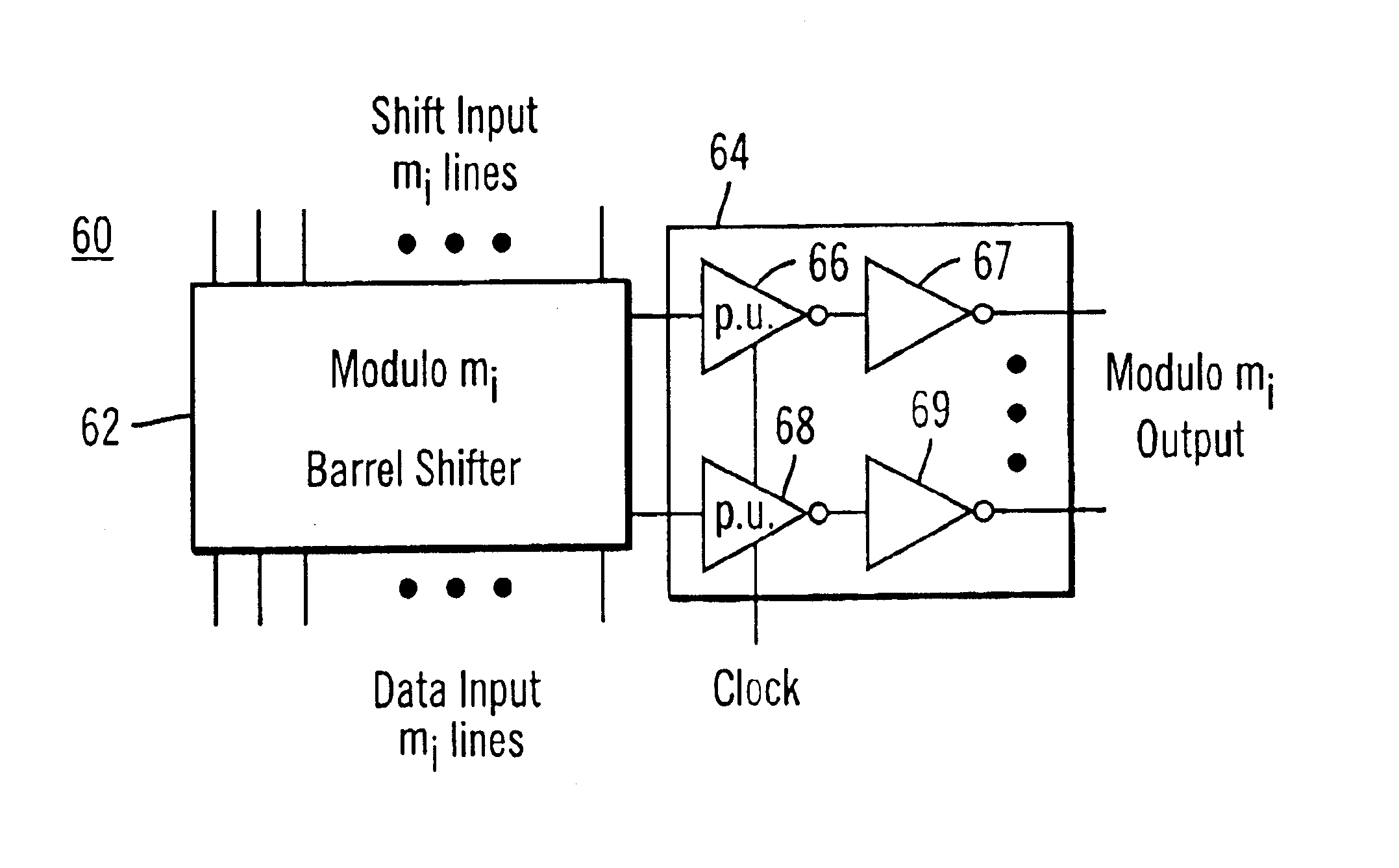
[0051]FIG. 8 shows an OHRNS modulo mi adder according to a preferred embodiment of the present invention. As shown, the adder 60 includes a barrel shifter 62 and a dynamic storage unit 64. The barrel shifter 62 computes the sum of the two operands as in the conventional OHRNS adder. In the illustrated embodiment, the dynamic storage unit 64 includes two cascaded inverter stages 66 and 67 for each output line of the barrel shifter 62. The cascaded inverter stages 66 and 67 dynamically latch the output of the barrel shifter 62 for downstream circuits by using a clocked inverter 66 as the first inverter in the cascade.

[0052]A preferred embodiment of the clocked inverter is shown in FIG. 9. The clocked inverter 70 has two PMOS transistors 72 and 74 and two NMOS transistors 76 and 78 arranged in series between the supply voltage Vdd and ground. The gates of...


PUM


Abstract

A modulo mi adder and a modulo mi,j scaling unit for use with an RNS. The adder includes a modulo mi barrel shifter, and a dynamic storage unit coupled to the barrel shifter to store the output of the barrel shifter. In a preferred embodiment, the dynamic storage unit includes one dynamic latch for each output line of the barrel shifter, with each of the dynamic latches including a clocked inverter in cascade with an inverter. One modulo mi,j scaling unit includes a modified modulo mi barrel shifter that performs both residue conversion and an arithmetic operation. The residue conversion is performed without using combinational logic. In one preferred embodiment, the modified barrel shifter performs the residue conversion though mi-mj additional columns that replicate normal columns for all modulo mi input lines that are congruent modulo mj. Another modulo mi,j scaling unit includes a barrel shifter-based arithmetic circuit, and a dynamic storage unit coupled to the arithmetic circuit to store the output of the arithmetic circuit.

Description

BACKGROUND OF THE INVENTION[0001]1. Field of the Invention[0002]The present invention relates to electronic circuits, and more specifically to arithmetic circuits for use with the residue number system.[0003]2. Description of Related Art[0004]Power consumption is now becoming a more important consideration in integrated circuit design. This has compelled circuit designers to consider reducing power consumption through changes in many different levels of the design process, such as the system, technology, algorithm, physical, and circuit levels. For example, system level approaches include power supply voltage scaling, clock gating, and subsystem sleep (or power down) modes. Technology level techniques include using dynamic threshold MOSFETs, and algorithm level techniques include using alternate number systems and state encoding. Further, physical level methods include transistor reordering, and circuit level methods include self-timed asynchronous approaches and glitch reduction. T...

Claims


Application Information

Patent Timeline
Patent Type & Authority Patents(United States)
IPC IPC(8): G06F7/38G06F5/01G06F7/72
CPCG06F7/729G06F5/01
Inventor ROBINSON, STEVEN R.CHREN, JR., WILLIAM A.
Owner STMICROELECTRONICS SRL
Why Eureka
Try Eureka