
In-situ plasma etch for TERA hard mask materials

a technology of tera mask and in-situ plasma etching, which is applied in the field of semiconductor processing, can solve the problems of increasing the cost and complexity of using tera hard mask/arc layers, the difficulty of in situ stripping of tera mask materials and the difficulty of stripping in situ when fluorine based processing is used

Inactive Publication Date: 2005-06-07
IBM CORP
View PDF26 Cites 15 Cited by
  • Summary
  • Abstract
  • Description
  • Claims
  • Application Information

AI Technical Summary

Benefits of technology

[0009]In accordance with the invention, a method is provided which includes the step of exposing the TERA material to a plasma containing an effective amount of nitrogen. The nitrogen binds the carbon in the TERA material, forming volatile species and thereby removing the carbon from the TERA material. The plasma may further contain oxygen or fluorine. If the plasma contains fluorine, the plasma preferably has a F / (N+O) ratio less than 0.25 or 0.1. A low fluorine content tends to provide selectivity over oxide.

Problems solved by technology

Since TERA is resistant to fluorine-based plasma etches, it is difficult to strip in situ when fluorine based processing is used.
In particular, semiconductor manufacturers are currently experiencing difficulty in stripping TERA mask materials without also damaging underlying layers.
This increases the cost and complexity of using TERA hard mask / ARC layers, which are otherwise highly desirable.
TERA materials can also be etched simultaneously with the nitride etch, but this approach causes other problems.
Specifically, sidewalls in the nitride layer can become sloped, which can be undesirable for certain devices.
This is primarily due to the additional C and Si load of the residual mask on the nitride etch process.
It is not practical to strip the TERA material with the same process used to pattern it from the resist mask because this unfavorably alters the profile of the oxide etch.
Therefore, in the state of the art, there appears to be no simple, practical method for stripping TERA materials in a processing system employing fluorine chemistry.

Method used


Image

  • In-situ plasma etch for TERA hard mask materials
  • In-situ plasma etch for TERA hard mask materials
  • In-situ plasma etch for TERA hard mask materials

Examples


Embodiment Construction

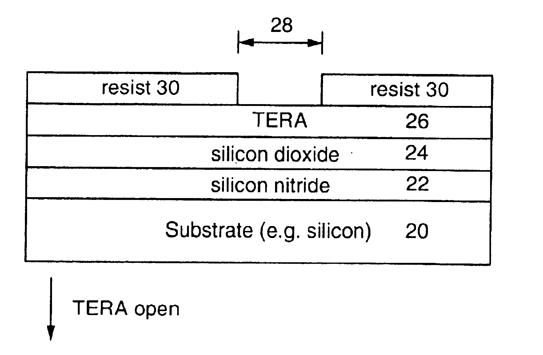
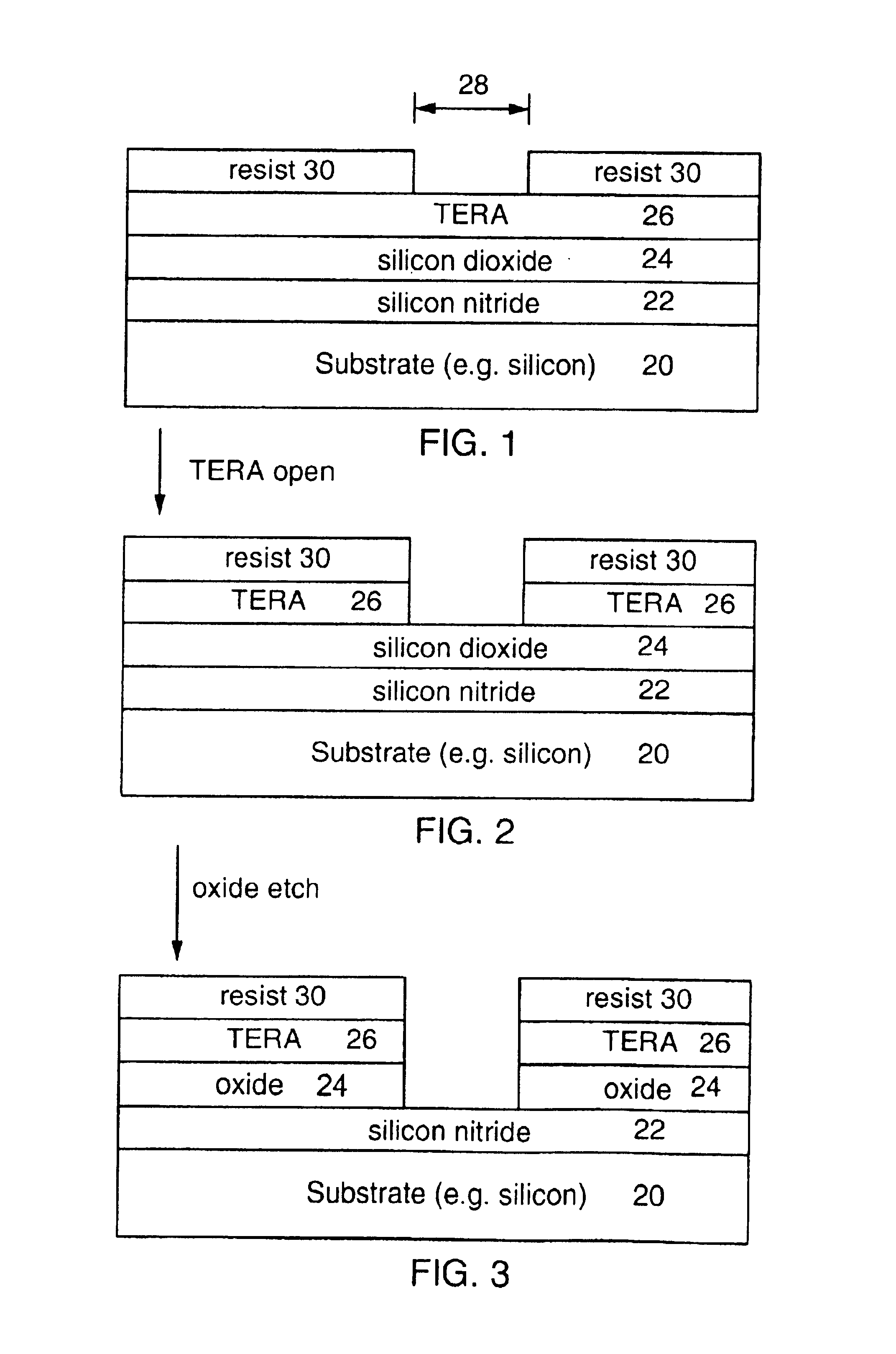
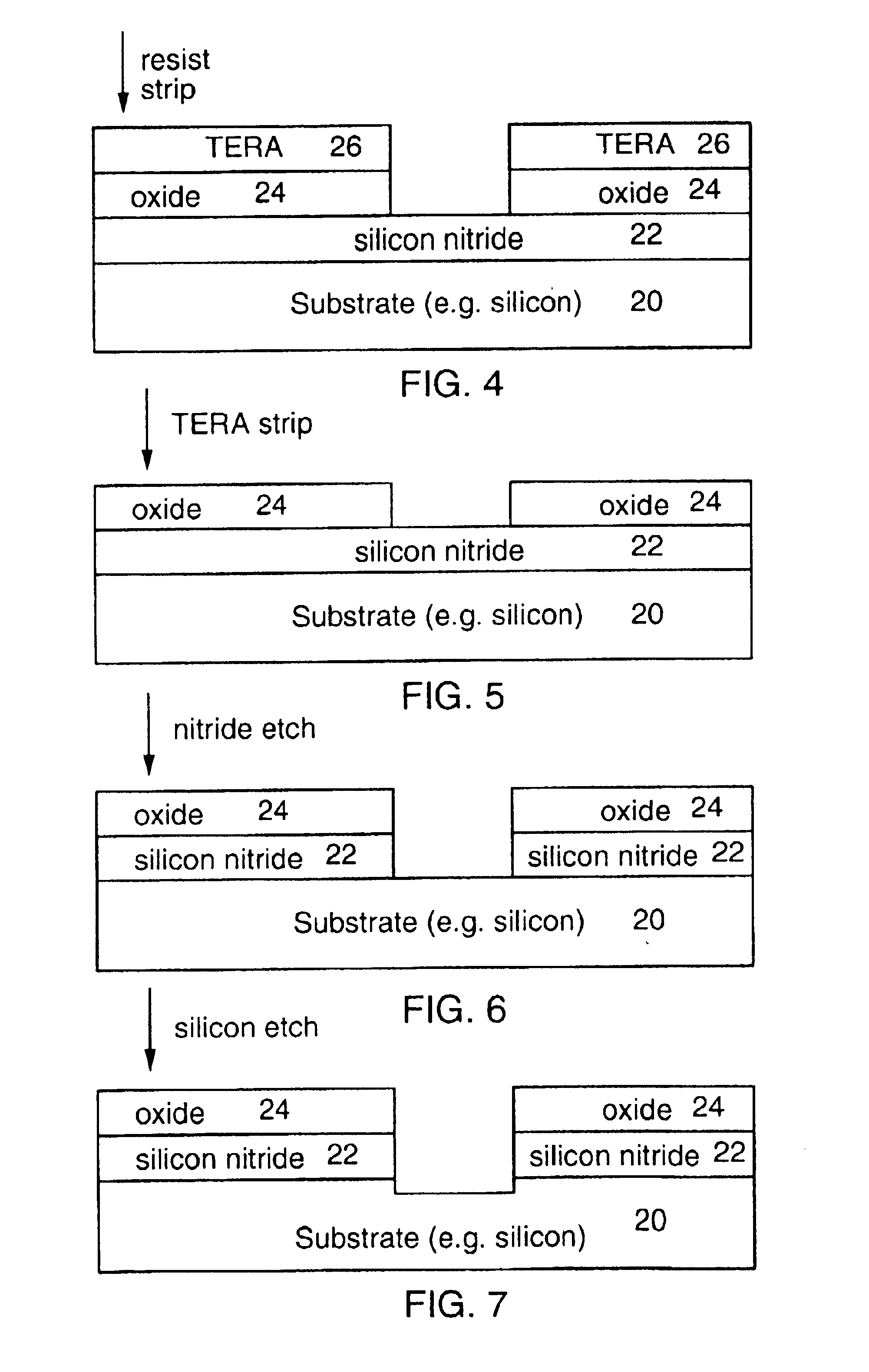
[0022]The present invention provides a method for etching TERA materials in a system employing or compatible with fluorine based etching plasmas. It has been discovered that the addition of nitrogen to an oxygen plasma provides a high etch rate of TERA materials. Oxygen and nitrogen plasmas are compatible with fluorine-based etching systems (that is, they do not erode silicon mechanical components), so the wafer does not need to be removed from the fluorine system to remove the TERA layer. Nitrogen / oxygen plasmas also do not cause formation of undesired profiles in underlying oxide and nitride films. Without being limited to a specific mechanism for this effect, it is believed that the enhanced etch rate caused by adding nitrogen to an oxygen plasma is caused by weakening or breakage of silicon-carbon bonds in the TERA material. In the present inventive method, carbon is removed from the TERA film due to the presence of nitrogen, rendering the film more etchable in the oxygen plasma...


PUM

PropertyMeasurementUnit
poweraaaaaaaaaa
energyaaaaaaaaaa
sizeaaaaaaaaaa

Abstract

A method for removing carbon from or stripping a TERA layer. The method includes exposing the TERA layer to a plasma containing an effective amount of nitrogen, and, optionally, oxygen or fluorine. The method is compatible with fluorine based etching systems, and may thus be performed in the same etching system as other etching steps. For example, the method may be performed in the same system as a fluorine based plasma etch for oxide or nitride. The invention includes the method of stripping a TERA layer, etching an oxide layer, and etching a nitride layer in situ in the same etching system. The method is performed at low ion energies to avoid damaging oxide or nitride layers under the TERA film and to provide good selectivity.

Description

FIELD OF THE INVENTION[0001]The present invention relates generally to semiconductor processing. More particularly, it relates to a method for selectively etching materials used as hard masks and antireflection coatings.BACKGROUND OF THE INVENTION[0002]For a number of reasons, increasing device density in semiconductor devices requires the use of photoresist having a reduced thickness. Since resist may be too thin to use for patterning directly, hard mask materials such as TERA (Tunable Etch-Resistant ARC, where ARC stands for Anti-Reflection Coating) have been developed to enable patterning. The photoresist is used only to image a thin hardmask material, which subsequently serves as a pattern transfer mask for underlying films (e.g. silicon dioxide, silicon nitride and the like). TERA hard mask layers can in some applications provide simultaneous hard mask and ARC functionality.[0003]TERA materials are defined as R—C—H—X, where R is selected from Si, Ge, B, and Sn; X is selected fr...

Claims


Application Information

Patent Timeline
Patent Type & Authority Patents(United States)
IPC IPC(8): H01L21/02H01L21/70H01L21/308H01L21/768H01L21/311G03F7/09H01L21/3065
CPCG03F7/091H01L21/3081H01L21/76802H01L21/31138H01L21/31144H01L21/31116H01L21/3065
Inventor WISE, RICHARD S.DESHPANDE, SADANAND V.YAN, WENDYALLEN, SOCTT D.MAHOROWALA, ARPAN P.
Owner IBM CORP
Learn More