Reinforcement butt stud welding method and device therefor and repairing/expanding method for ferroconcrete structure

a technology of reinforced butt studs and welding methods, which is applied in the direction of bridges, soldering devices, building repairs, etc., can solve the problems of collapse, major social problems, and the majority of structures built in the period

Inactive Publication Date: 2005-06-14
IHI CONSTR SERVICE
View PDF11 Cites 5 Cited by
  • Summary
  • Abstract
  • Description
  • Claims
  • Application Information

AI Technical Summary

Benefits of technology

[0083]With the reinforcement butt stud welding method in accordance with the first aspect of the present invention, reinforcements of approximately the same diameter can be welded together and good welding can be conducted even when the reinforcements are in an almost horizontal state. In particular, when an existing ferroconcrete structure is partially cut and a new ferroconcrete portion is constructed in the cut part, the operation of concrete breaking can be substantially reduced, the term of works can be shortened, and noise generation can be decreased. In addition, using a stud base allows thermal damage of the earth clamp to be restricted and the earth clamp to be used repeatedly. Therefore, a contribution is made to cost reduction and good stud welding can be conducted.
[0084]With the stud welding apparatus in accordance with the second aspect of the present invention, the gun structure is such that the entire length in a state in which a stud reinforcement has been mounted on the stud gun is determined by the length of the stud reinforcement itself. Therefore, a stud reinforcement can be coaxially butt welded to the end portion of a horizontally laid existing reinforcement in a work space which is substantially narrower than that required for the conventional structures and a good welding state can be obtained.
[0085]With the repairing / expanding method for a ferroconcrete structure in accordance with the third aspect of the present invention, the operation of concrete breaking can be substantially reduced, the term of works can be shortened, and noise generation can be decreased. Furthermore, the quantity of generated industrial waste is greatly decreased, thereby limiting the waste processing cost and greatly improving the state of construction site. In addition, the breaking quantity of concrete after cutting can be restricted to less than about ⅕ that of the conventional process, the period of noise generation during this operation can be greatly shortened, and shortening of the term of works is also significant.
[0086]Moreover, the term of works in replacing an expansion unit disposed in a joint portion of concrete deck slabs of a bridge, lateral width expanding the deck slabs of a bridge, and reinforcing and modifying the internal surface of a tunnel can be greatly shortened, the traffic restriction period can be shortened, and the effect produced on industrial activity using the road can be decreased. In particular, when the construction work is conducted in an urban area, the effect on the residents in the neighborhood can be also decreased.

Problems solved by technology

In recent years, collapses have been occurring frequently in ferroconcrete viaducts and tunnels of the Shinkansen Line and have become a serious social problem.
Ferroconcrete structures are expected to have a service life of no less than 50 years, but most of the structures built in the period of high growth of Japanese economy are approaching the life limit because of worsening of the environment surrounding the ferroconcrete structures.
The most troublesome of those operations is breaking the concrete.
For this reason, the breaking process is often extended far into the night and the generated noise greatly annoys people living nearby.
Furthermore, in case of extreme noise, the operation itself is sometimes interrupted because of complaints from people living nearby or by use of force.
21(d) also was the major problem in terms of extending the work time and generating noise.
The operation of joining the reinforcements in this case required much time and labor, making it difficult to reduce cost.
However, this welding operation takes much time and has poor operation efficiency making it unsuitable for commercial applications.
However, welding a reinforcement with a diameter of 20 mm requires a lapping allowance of about 80 cm and is unsuitable for replacement of expansion unites or lateral width expansion of deck slabs.
For this reason, the operations of welding the reinforcements of about the same diameter to each other and welding the reinforcements in an almost horizontal state thereof were absolutely unimaginable within a framework of the conventional stud welding technology.
As a result, a minimum space is required of a size obtained by adding the stud length to the length to the distal end of the drive shaft of the stud gun, and setting itself becomes especially difficult when a long shaped reinforcement is used.

Method used


Image

  • Reinforcement butt stud welding method and device therefor and repairing/expanding method for ferroconcrete structure
  • Reinforcement butt stud welding method and device therefor and repairing/expanding method for ferroconcrete structure
  • Reinforcement butt stud welding method and device therefor and repairing/expanding method for ferroconcrete structure

Examples


first embodiment

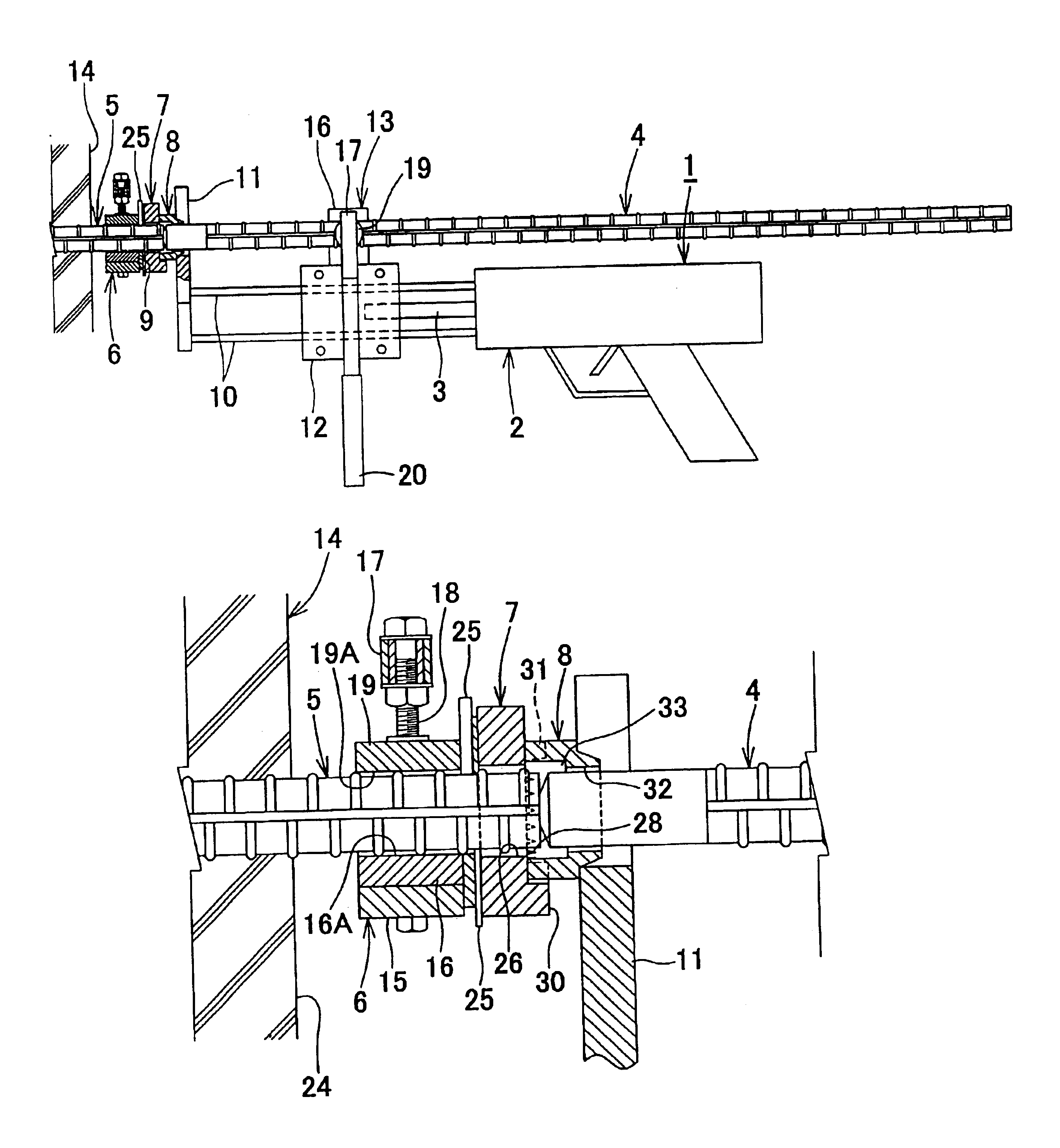
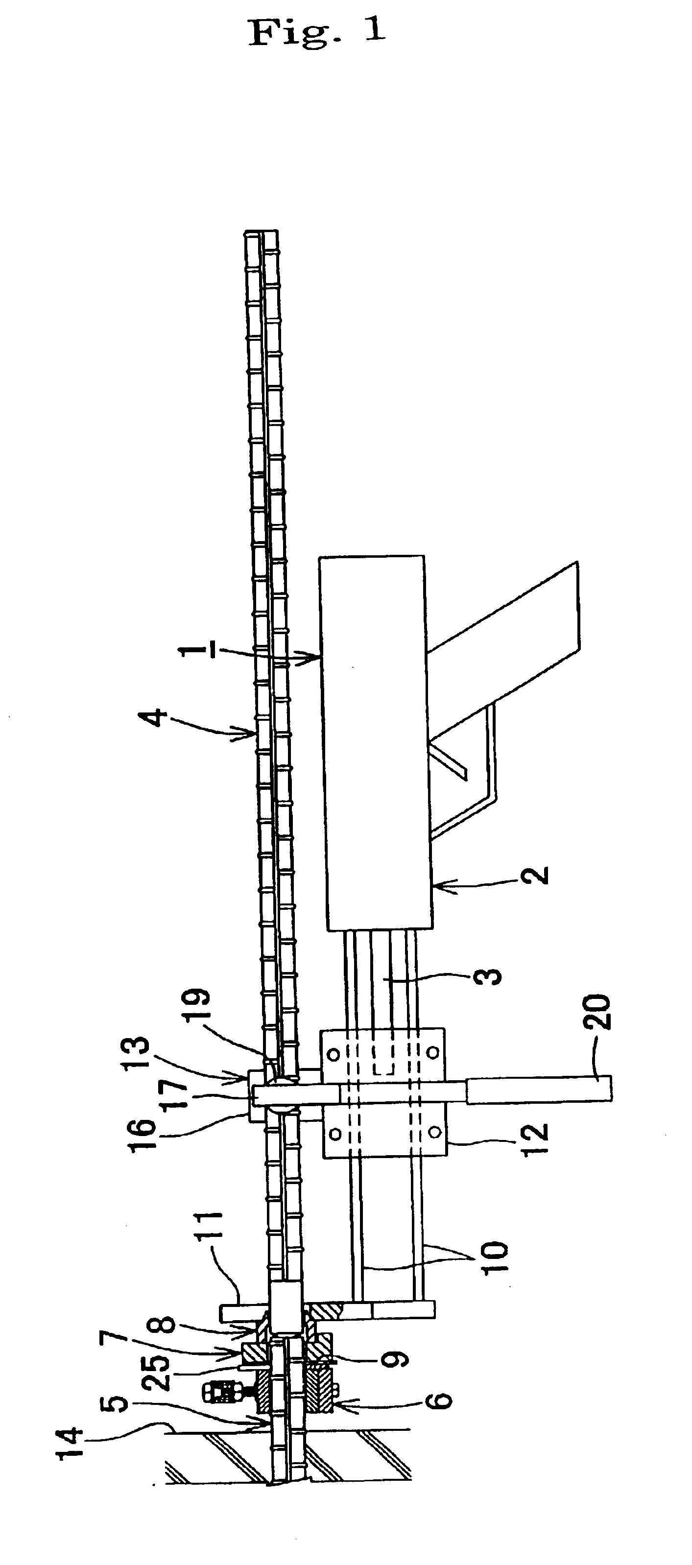
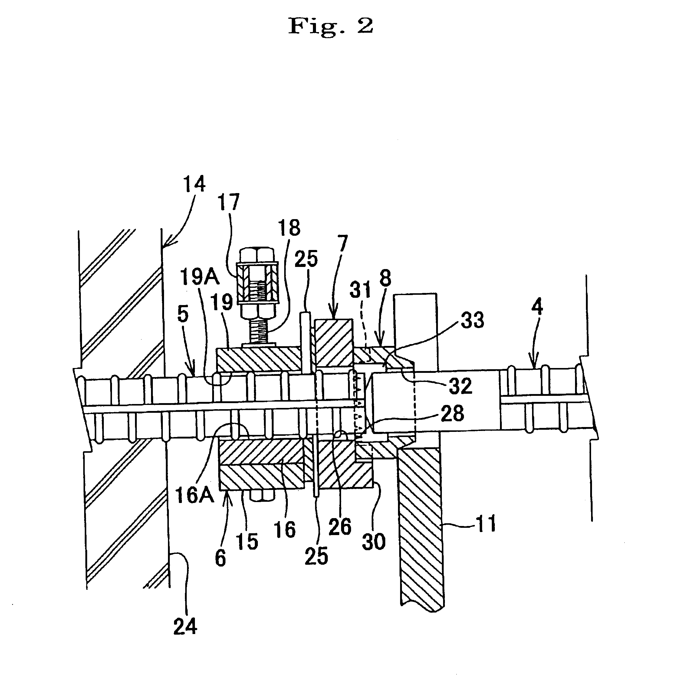
[0046]The embodiments of the present invention will be described below in greater details based on the appended drawings. FIGS. 1 through 5 illustrate the stud welding apparatus in accordance with the present invention. In the figures, the reference symbol 1 stands for a stud gun, 2—a gun body, 3—a drive shaft, 4—a stud reinforcement, 5—an existing reinforcement, 6—an earth clamp, 7—a stud base, and 8—a ferrule.

[0047]The stud gun 1 of the first embodiment constituting the stud welding apparatus in accordance with the present invention has a basic configuration in which one or a plurality of guide poles 10, 10 are provided in a protruding condition, parallel to the drive shaft 3 for linear driving, in front of the stud gun body 2, a ferrule contact part 11 is formed on the distal ends of the guide poles 10, 10, a movable body 12 slidably provided in the middle portion of the guide poles 10, 10 is linked to the drive shaft 3, a stud holding tool 13 is provided on the movable body 12, ...

embodiment 1

[0065]Another embodiment of the stud gun 1 will be explained below based on FIGS. 12 through 14. The stud gun 1 shown in FIG. 12 is a modification of the stud gun of In case of a long stud reinforcement 4, holding the stud reinforcement 4 only with the stud holding tool 13 sometimes becomes unstable. In this case, as shown in FIG. 12, one or a plurality of second guide poles 47, 47 are provided in a protruding condition parallel to the drive shaft 3 behind the gun body 2, a second stud holding tool 49 is provided on a second movable body 48 slidably provided on the second guide poles 47, 47, and the stud reinforcement 4 is arranged above the gun body with the front stud holding tool 13 and rear second stud holding tool 49. Further, if a transverse orientation of stud holding tool 13 and second stud holding tool 49 is set (this configuration is not shown in the figures), the stud reinforcement 4 can be arranged on the side of gun body 2. Other aspects of this configuration are ident...

second embodiment

[0066]stud gun 1 will be explained below based on FIG. 13. In the stud gun 1 of the present embodiment, a stud holding tool 50 is transversely provided on the distal end portion of drive shaft 3 for linearly driving the stud gun body 1, a linear guide 51 is provided parallel to the drive shaft 3 along the upper surface of gun body 2, an auxiliary stud holding tool 52 is slidably provided on the linear guide 51, a ferrule contact member 53 is provided on the distal end in front of gun body 2, and the stud reinforcement 4 mounted on the stud holding tool 50 and auxiliary stud holding tool 52 is arranged above the gun body. It is also possible to arrange the stud holding tool 50 sidewise, to provide the linear guide 51 on the side of gun body 2, and to arrange the stud reinforcement 4 on the side of the gun body (this configuration is not shown in the figures). Other aspects of this configuration are identical to those shown in FIG. 1. Identical components are assigned with the same re...


PUM

PropertyMeasurementUnit
thicknessaaaaaaaaaa
distanceaaaaaaaaaa
diameteraaaaaaaaaa

Abstract

A reinforcement butt stud welding method and a device therefore, capable of butt-welding a stud reinforcing bar coaxially to the end portion of a horizontally-laid existing reinforcement in a small work space; and a repairing / expanding method for a ferroconcrete structure. The reinforcement butt stud welding method includes the steps of fitting an earth clamp over the periphery of the end portion of the existing reinforcement, fitting an annular stud base that is a heat-resisting, insulating material to the conductor surface of the earth clamp by being pressed against the conductor surface, bringing the tip end of a stud reinforcing bar, loaded in a stud welding gun, into contact with the end face of the existing reinforcement, and keeping a ferrule disposed around the tip end portion of the stud reinforcing bar joined to the stud base to complete stud welding.

Description

TECHNICAL FIELD[0001]The present invention relates to a reinforcement butt stud welding method allowing for coaxial butt welding of a stud reinforcement to an end portion of a horizontally laid existing reinforcement in a narrow work space and an apparatus therefor, and also to a repairing / expanding method for ferroconcrete structure suitable for replacing an expansion unit disposed in a joint portion of deck slabs of a bridge, lateral width expanding the deck slabs of a bridge, or reinforcing and modifying the internal surface of a tunnel.BACKGROUND ART[0002]In recent years, collapses have been occurring frequently in ferroconcrete viaducts and tunnels of the Shinkansen Line and have become a serious social problem. Leaving aside the issue of causes of such collapses, ferroconcrete structures that had been built in rapidly increasing numbers in 1960-1970's that was a period of high growth of Japanese economy have been aging under the effect of exhaust gases of vehicles and acid rai...

Claims


Application Information

Patent Timeline
Patent Type & Authority Patents(United States)
IPC IPC(8): B23K11/04B23K11/02B23K9/20E04G21/12E01D22/00E04G23/02E04C5/16
CPCB23K9/20B23K9/202B23K11/02B23K11/04E04G23/02E01D22/00E04C5/163E04G21/122B23K11/046
Inventor NONAKA, HARUO
Owner IHI CONSTR SERVICE
Why Eureka
Try Eureka