Method for limiting the current in an electric motor, and a motor for carrying out one such method

a current limitation and electric motor technology, applied in the direction of dynamo-electric machines, single motor speed/torque control, ac motor stoppers, etc., can solve problems such as electrical losses in motors, and achieve the effects of simple current limiting, reducing electrical losses in motors, and reducing pulse duty factors

Inactive Publication Date: 2005-06-14
EBM PAPST ST GEORGEN & -
View PDF25 Cites 45 Cited by
  • Summary
  • Abstract
  • Description
  • Claims
  • Application Information

AI Technical Summary

Benefits of technology

[0005]According to the invention, this object is achieved by sensing when current exceeding a predetermined limit value occurs and responding by using semiconductor switches in a full bridge circuit to interrupt current flowing from the DC power network to the motor windings. The method according to the present invention for limiting current in a DC motor thus acts on a full bridge circuit through which the stator winding arrangement of that motor is supplied with current. When the current limiter responds, energy delivery to the stator winding arrangement from the DC power network is interrupted. The stator winding arrangement is then driven substantially in short circuit via semiconductor switches of the full bridge circuit, and the decaying current flowing in that context serves substantially to continue driving the motor. When that current has reached a lower value, energy delivery from the DC power network to the motor is once again activated. The result is that excessively high currents are avoided, and that when the current limiter responds, the energy stored in the inductance of the stator winding arrangement is converted principally into mechanical drive energy.
[0006]A preferred development of the invention is to deliver energy to the motor as pulse-width-modulated current and, when an overcurrent is sensed, to decrease the pulse duty factor. When the current limiter responds in this instance, the effective value of the current flowing to the motor is reduced, so that gradually a state is achieved in which the current limiter no longer needs to respond, at least for several rotor revolutions. Since the pulse content of the current becomes high when the current limiter responds, causing corresponding motor noise, this contributes to noise diminution and also reduces electrical losses in the motor.
[0007]In particularly preferred fashion, the duration of the current blocks conveyed to the stator winding arrangement is increased in order to compensate for the reduction in the effective current. The electrical power conveyed to the motor can thereby be kept substantially constant despite the reduction in effective current, since in this case the lower current flows for a longer time.
[0008]Another way of achieving the stated object is provided by an electric motor with a circuit which monitors the current flowing from a DC supply lead to a bridge transistor and, when an overcurrent is detected, controls a bridge transistor from a conductive state to a nonconductive state. Monitoring of the current flowing from a DC supply lead to a bridge transistor allows very simple current limiting, and prevents overloading of the motor.
[0009]It is particularly advantageous if an electric motor of this kind has means for turning on other bridge transistors connected to the second DC supply lead, since switching on the bridge transistors connected to the second DC supply lead causes the overcurrent in the stator winding arrangement to decrease rapidly, and to be converted largely into kinetic energy.

Problems solved by technology

Since the pulse content of the current becomes high when the current limiter responds, causing corresponding motor noise, this contributes to noise diminution and also reduces electrical losses in the motor.

Method used


Image

  • Method for limiting the current in an electric motor, and a motor for carrying out one such method
  • Method for limiting the current in an electric motor, and a motor for carrying out one such method
  • Method for limiting the current in an electric motor, and a motor for carrying out one such method

Examples


Embodiment Construction

[0044]In the description below, identical reference characters are used for identical or identically functioning parts, which are usually described only once. Since the subject is a difficult one, concrete numerical values—e.g. 3 A, 1.6 A, 200 μs, 1000 rpm, etc.—are often indicated in order to make the text more readable. It is understood as self-evident, however, that these concrete values are merely preferred examples which in no way limit the invention.

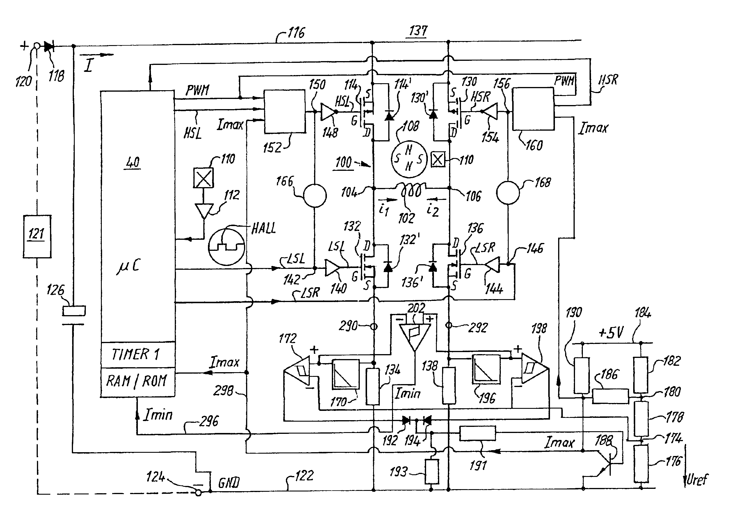
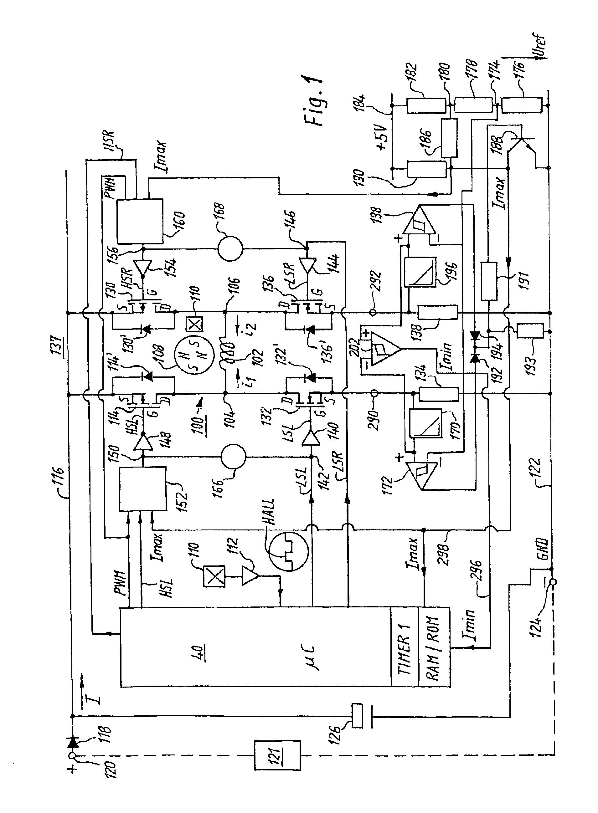
[0045]FIG. 1 provides an overview of a preferred embodiment of a motor according to the invention.

[0046]In this embodiment, the actual motor 100 has one winding phase 102 having two terminals 104, 106, as well as a permanent-magnet rotor 108. The exemplary embodiment below refers to a motor 100 having a four-pole rotor 108, although any number of poles, and also other numbers of winding phases, are of course possible. The example of motor 100 was selected because of its simplicity, in order to facilitate comprehension of this very ...


PUM


Abstract

A method of limiting current in a DC motor acts on a full bridge circuit (137) through which the stator winding arrangement (102) of that motor is supplied with current. Upon response of the current limiter, energy supply to the stator winding arrangement (102) from the DC power network is interrupted. The stator winding arrangement is then operated substantially in short circuit via semiconductor switches of the full bridge circuit, and the decaying current flowing in that context serves substantially to continue driving the motor. When that current has reached a lower value, energy supply from the DC power network to the motor is once again activated. The effective value of the current flowing to the motor is preferably reduced when the current limiter responds. The time period during which that current flows, in the form of current blocks, is then increased in compensatory fashion.

Description

[0001]This application is a § 371 of International Application PCT / EP01 / 15236, filed 21 Dec. 2001.FIELD OF THE INVENTION[0002]The invention concerns a method for limiting current in an electric motor, and a motor for carrying out such a method.BACKGROUND[0003]With modern motors, especially electronically commutated motors, a small overall size is desirable so that they can easily be installed in equipment, e.g. in fans. A motor of this kind has a high power density and operates in the vicinity of limit values that should not be exceeded. Such a motor is nevertheless expected to run quietly and with good electromagnetic compatibility (EMC).SUMMARY OF THE INVENTION[0004]It is therefore an object of the invention to make available a new method for limiting current in an electric motor, and a motor for carrying out such a method.[0005]According to the invention, this object is achieved by sensing when current exceeding a predetermined limit value occurs and responding by using semicondu...

Claims


Application Information

Patent Timeline
Patent Type & Authority Patents(United States)
IPC IPC(8): H02P6/00H02P6/08H02P6/26H02P6/28
CPCH02P6/002H02P6/085H02P6/008H02P2209/07H02P6/26H02P6/28
Inventor BERROTH, HANSJORGHAHN, ALEXANDERHELLER, FRANKJESKE, FRANKKARWATH, ARNOKUNER, ARNOLDSCHONDELMAIER, HANS-DIETERRAPPENECKER, HERMANNSTRASSER, GUNTHER
Owner EBM PAPST ST GEORGEN & -
Why Eureka
Try Eureka