
Display device comprising a light guide

Inactive Publication Date: 2005-06-21
KONINKLIJKE PHILIPS ELECTRONICS NV
View PDF7 Cites 7 Cited by
  • Summary
  • Abstract
  • Description
  • Claims
  • Application Information

AI Technical Summary

Benefits of technology

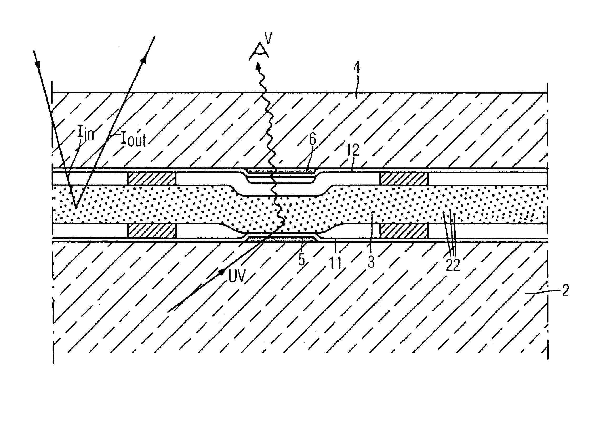
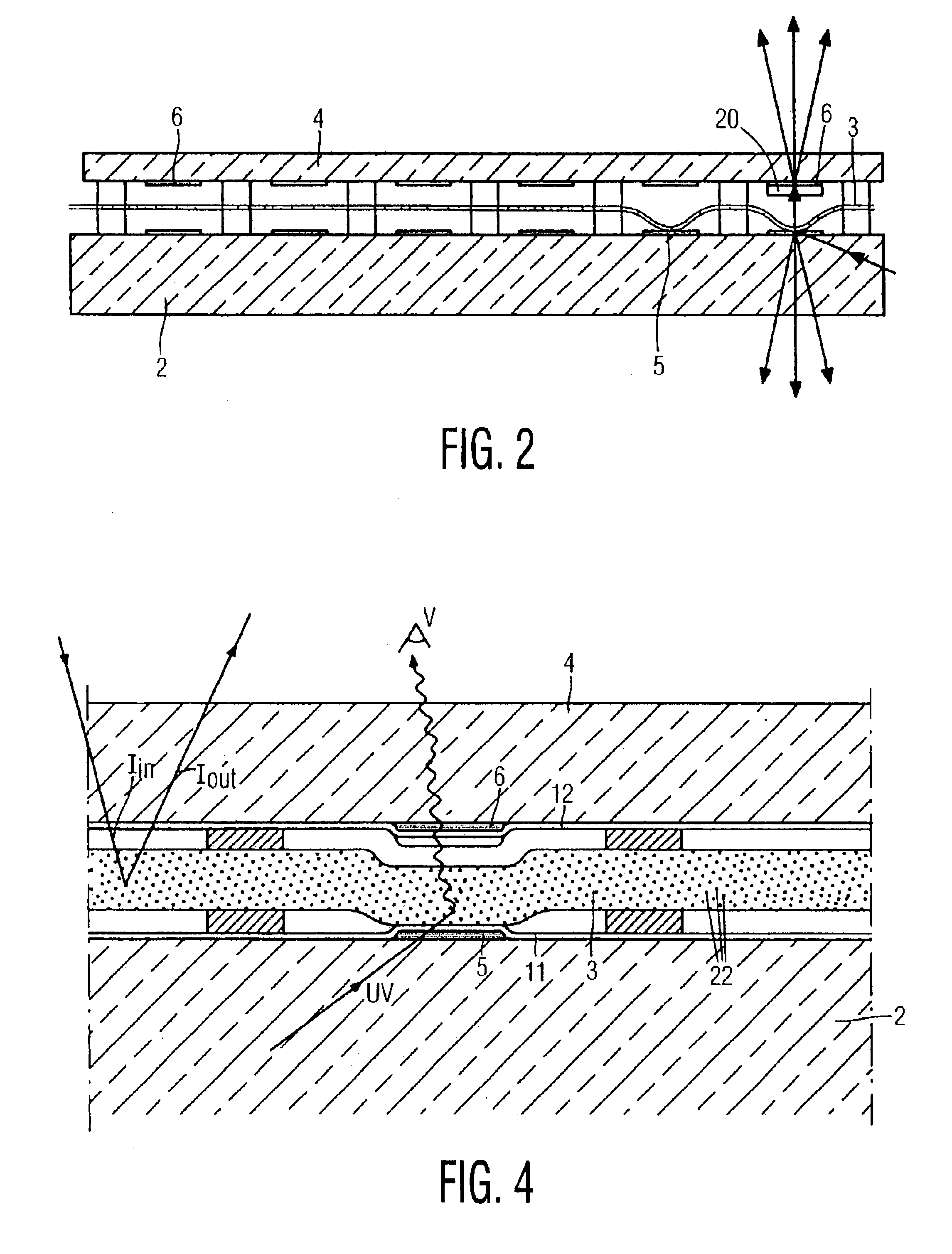
[0008]By using UV excitable phosphor elements for generating different colors, it is possible to generate a color image. When the movable element is in contact with the light guide, the scattering centers in the movable element scatter the UV light out of the light guide, which UV light excites a phosphor element. The use of phosphors emitting different colors provides a color display device which uses a single type of light source. It is not necessary to use three different types of light sources (one for each color) or to use color filters for extracting colored light from white light, which inevitably results in appreciable losses of intensity.
[0009]By placing the phosphor particles in an embedding material (also called matrix), the scattering of all light including visible light by the phosphor element is reduced when using phosphor particles in the usual powder form. The difference in index of refraction between the phosphor particles and its surrounding medium is decreased, which reduces the scattering. In the preferred embodiment, the average size is small (smaller than λ / π, most preferably between λ / 6π and λ / 2π) which reduces the scattering. The UV absorption is roughly proportional to a / λ, whereas the scattering is much more strongly reduced as the size of the particles decreases. In the indicated range for the size of the phosphor particles, an efficient UV absorption is combined with a strongly reduced visible light scattering efficiency.
[0013]In preferred embodiments, the average size a of the scattering particles in the movable element is smaller than λ / π, where λ is the wavelength of the UV radiation emitted by the source. For UV sources emitting UV light in lines, ‘the wavelength’ is the most prominent component of the spectrum emitted by the source. For UV sources emitting a continuous spectrum, ‘the wavelength’ is the peak of the continuous spectrum. For particles, the scattering efficiency (when in a matrix) is reduced sharply (roughly by a factor of (a / λ)k (k between 2 and 4)) for wavelengths larger than a. If e.g. λ=380 nm and a / λ<<1, then k=4 and the scattering efficiency for green light (λ=550 nm) is a factor of 4.4 less than that for UV. Preferably, at least 90% of the particles is smaller than λ / π. The most preferred range for the average particle size a lies between λ / 6π and λ / 2π. If the particles become smaller than λ / 6π, the scattering efficiency for UV light decreases strongly. The reduced scattering can be overcome by increasing the number of particles (the density of the particles). This may lead, however, to agglomeration of the particles, the agglomerates forming, in effect, particles of a much larger size, for which the visible light scattering efficiency may be high.
[0014]In embodiments of the invention as regards its second aspect, the difference in index of refraction of the scattering particles and the embedding material is larger in UV than in visible light, preferably at least √2 larger. The larger the difference in index of refraction, the greater the scattering. By choosing scattering particles and embedding materials for which the difference in index of refraction is larger in UV than in visible light, the ratio of the scattering efficiencies in UV and in visible light is larger than one, thus increasing contrast.
[0016]By providing the phosphor particles directly in or on the movable element, the design is simplified, because separate phosphor-comprising elements need no longer be used. Compared to embodiments in which the UV light is scattered in the movable element, exits this element and thereafter impinges on phosphor elements, no scattering particles are needed, which reduces the scattering of visible light, and more of the UV light can be used for exciting the phosphors, thus reducing the amount of phosphor material needed and thus further reducing scattered light by reducing the light scattered by the phosphor particles. By embedding the phosphor particles in the material of the movable element, scattering of visible light is further reduced. The indicated size ranges provide an even further reduced scattering of visible light.

Problems solved by technology

Light which is incident on the display screen of the display is reflected and reduces the visibility of, or blurs the image displayed on the display screen.
It is not necessary to use three different types of light sources (one for each color) or to use color filters for extracting colored light from white light, which inevitably results in appreciable losses of intensity.
The inventors have realized that the nature of the particles for scattering may pose a problem in relation to contrast.
Thus, the UV light is coupled out of the light guide by scattering in an efficient manner, and yet incident light is much less efficiently scattered.

Method used


Image

  • Display device comprising a light guide
  • Display device comprising a light guide
  • Display device comprising a light guide

Examples


Embodiment Construction

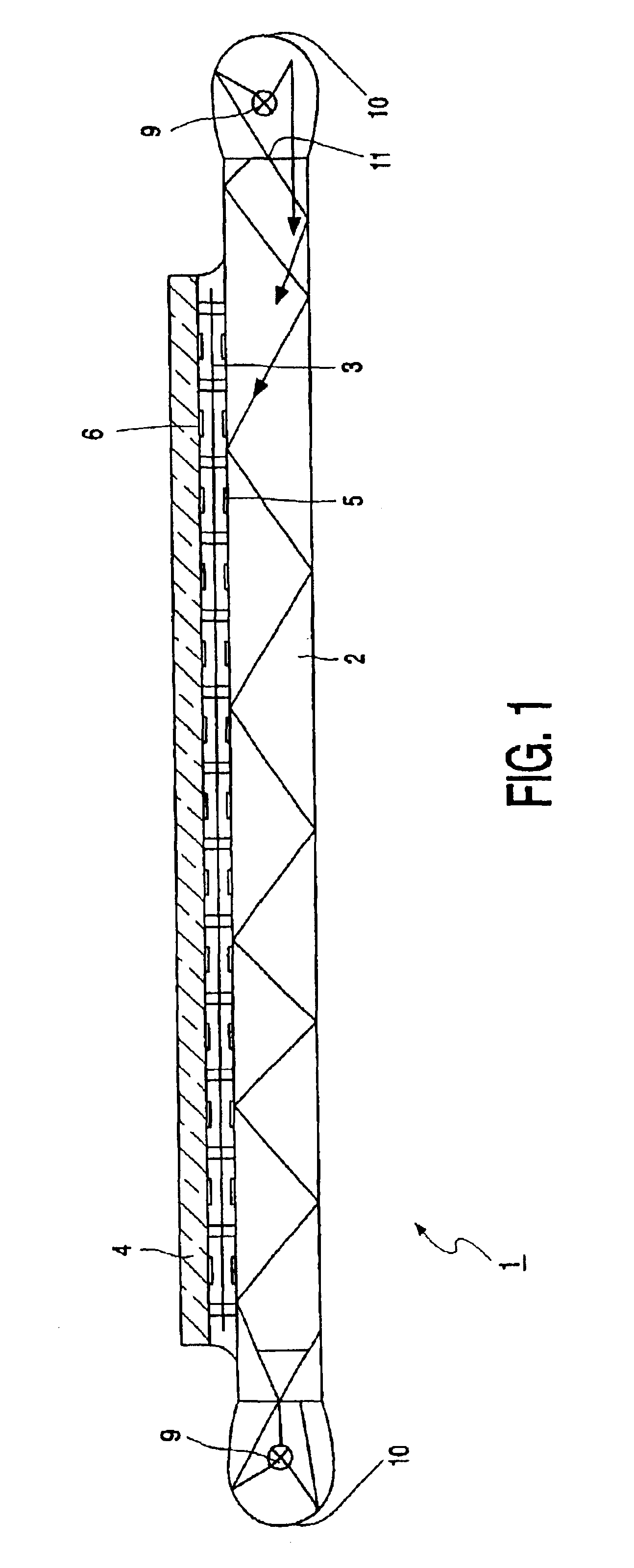
[0024]FIG. 1 schematically shows a display device 1 in accordance with the invention. Said display device comprises a light guide 2, a movable element 3 and a second plate 4. Electrode systems 5 and 6 are arranged, respectively, on the sides of the light guide 2 and the second plate 4 facing the movable element 3. By locally generating a potential difference between the electrodes 5, 6 and the movable element 3, by applying, in operation, electric voltages to the electrodes and the movable element forces are locally exerted on the movable element, which pull the movable element against the light guide or keep it at a distance from the light guide, preferably against the second plate 4. The display device further comprises a light source 9 which in operation emits UV light. Reflectors 10 are provided. FIG. 2 shows how the movable element 3 lies against the light guide 2. In this state, a portion of the UV light enters the movable element. In this movable element, the UV light is scat...


PUM


Abstract

A display device includes an ultraviolet light (UV light) source, a light guide; a movable element; phosphor elements, including phosphor particles in an embedding material, that emit visible light at different colors when excited by UV light; and electrodes arranged so that electric voltage applied to the electrodes can generate an electric field to move the movable element into contact with the light guide to couple light out of the light guide.

Description

CROSS REFERENCE TO RELATED APPLICATIONS[0001]This is a continuation of application Ser. No. 09 / 510,142, filed Feb. 22, 2000 now U.S. Pat. No. 6,528,937.FIELD OF TECHNOLOGY[0002]The invention relates to a display device with a light source and a display part comprising a light guide, a movable element and selection means to locally and selectively bring said movable element into contact with the light guide to couple light out of the light guide.BACKGROUND AND SUMMARY[0003]A display device of the type mentioned in the opening paragraph is known from U.S. Pat. No. 4,113,360.[0004]In said patent, a description is given of a display device comprising a first plate of a fluorescent material, in which, in operation, light is generated and trapped (so that this plate forms a light guide), a second plate which is situated at some distance from the first plate and, between said two plates, a movable element in the form of a membrane. By applying voltages to addressable electrodes on the firs...

Claims


Application Information

Patent Timeline
IPC IPC(8): F21V8/00G02B26/02G09F9/37
CPCG02B6/0011G02B26/02G02B6/0068G02B6/0036
Inventor VAN GORKOM, GERARDUS G. P.
Owner KONINKLIJKE PHILIPS ELECTRONICS NV
Learn More