Expandable stents and method for making same

Inactive Publication Date: 2005-06-21
ABBOTT CARDIOVASCULAR
View PDF211 Cites 26 Cited by
  • Summary
  • Abstract
  • Description
  • Claims
  • Application Information

AI Technical Summary

Benefits of technology

[0013]The elongated elements which interconnect adjacent cylindrical elements should have a transverse cross-section similar to the transverse dimensions of the undulating components of the expandable cylindrical elements. The interconnecting elements may be formed in a unitary structure with the expandable cylindrical elements from the same intermediate product, such as a tubular element, or they may be formed independently and connected by suitable means, such as by welding or by mechanically securing the ends of the interconnecting elements to the ends of the expandable cylindrical elements. Preferably, all of the interconnecting elements of a stent are joined at either the peaks or the valleys of the undulating str

Problems solved by technology

One of the difficulties encountered using prior stents involved maintaining the radial rigidity needed to hold open

Method used


Image

  • Expandable stents and method for making same
  • Expandable stents and method for making same
  • Expandable stents and method for making same

Examples


Example

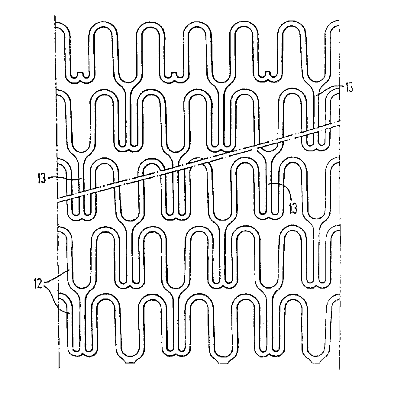
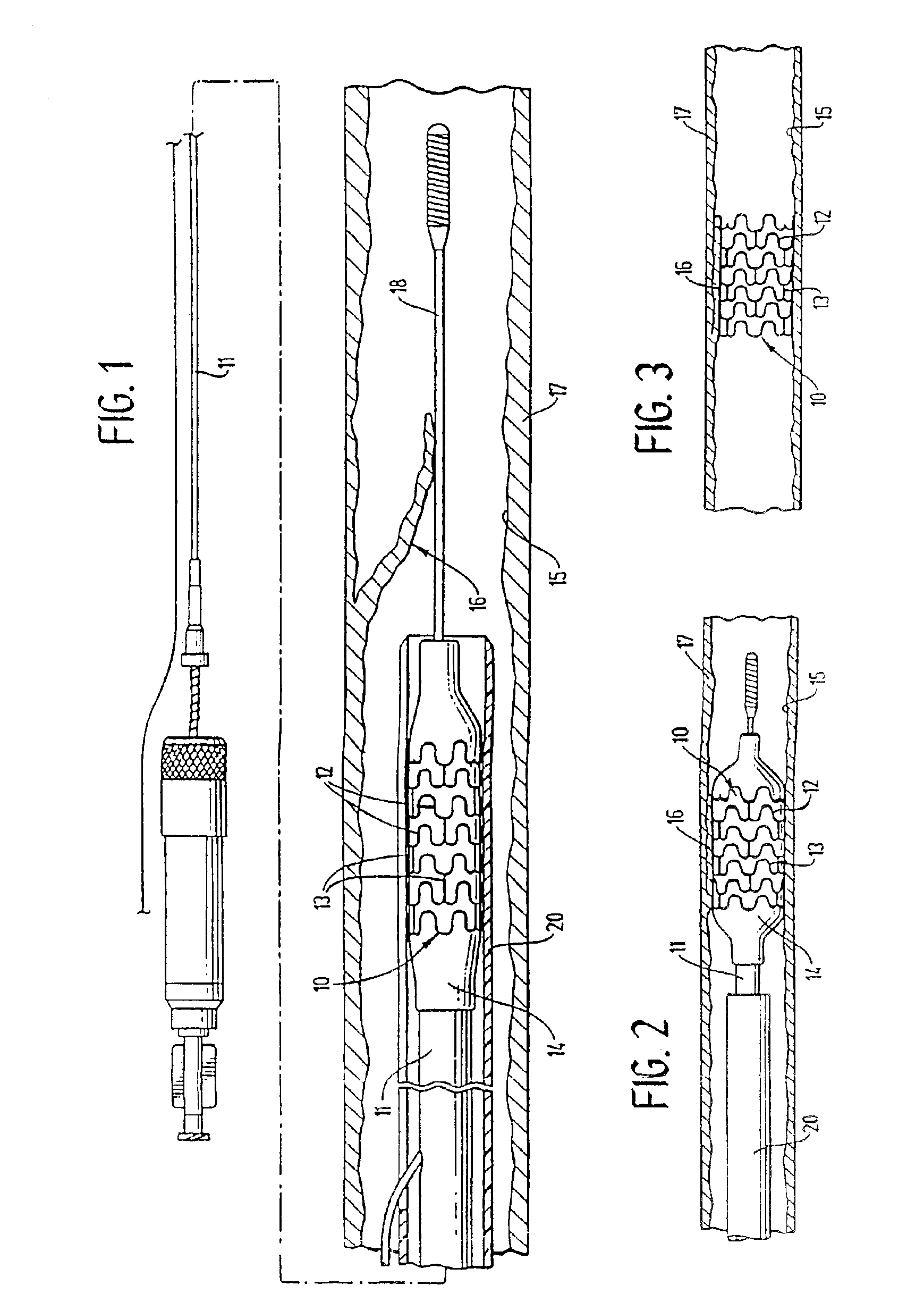
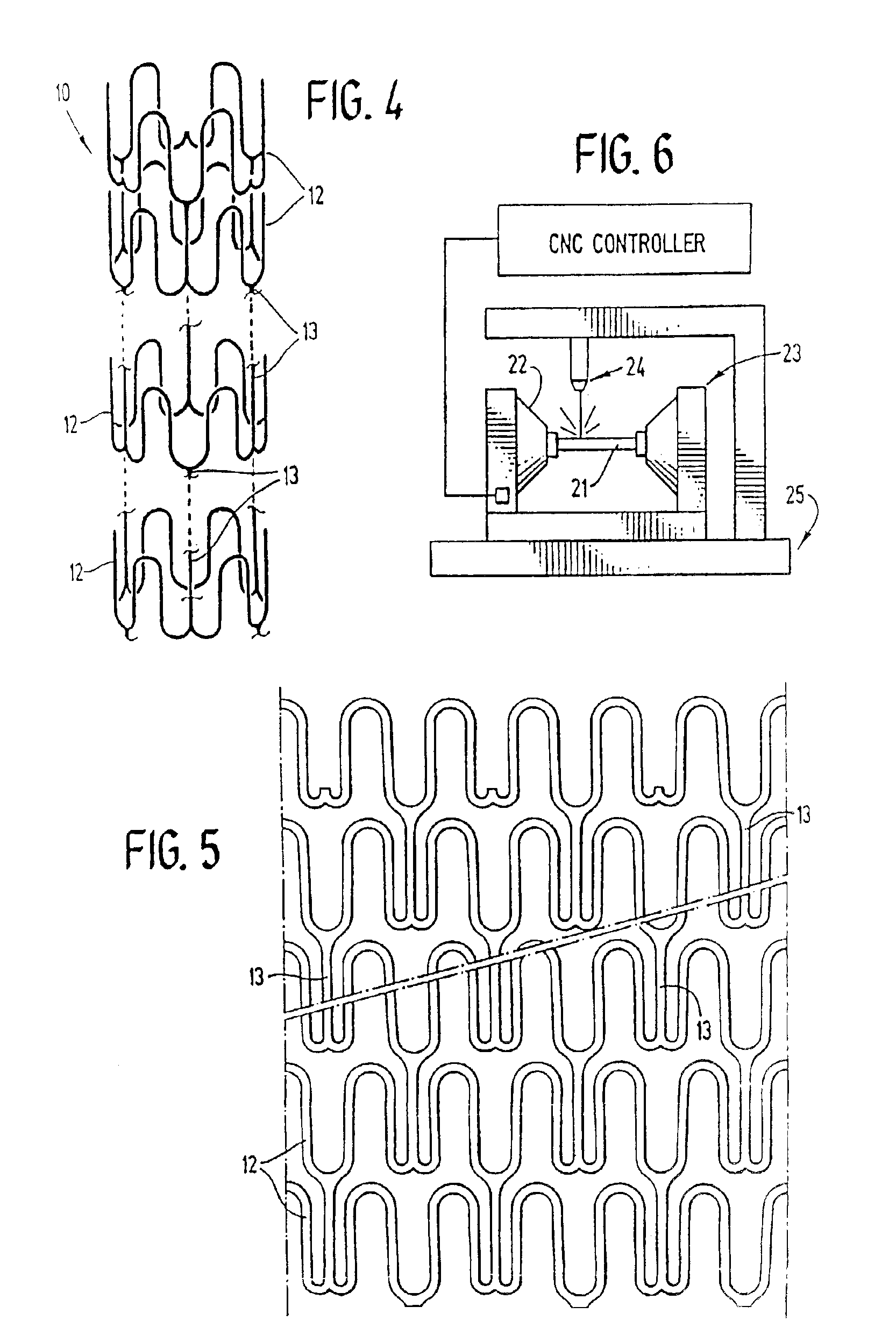
[0028]FIG. 1 illustrates a stent 10 incorporating features of the invention which is mounted onto a delivery catheter 11. The stent generally comprises a plurality of radially expandable cylindrical elements 12 disposed generally coaxially and interconnected by elements 13 disposed between adjacent cylindrical elements. The delivery catheter 11 has an expandable portion or balloon 14 for expanding of the stent 10 within an artery 15. The artery 15, as shown in FIG. 1 has a dissected lining 16 which has occluded a portion of the arterial passageway.

[0029]The delivery catheter 11 onto which the stent 10 is mounted, is essentially the same as a conventional balloon dilatation catheter for angioplasty procedures. The balloon 14 may be formed of suitable materials such as polyethylene, polyethylene terephthalate, polyvinyl chloride, nylon and ionomers such as Surlyn® manufactured by the Polymer Products Division of the Du Pont Company. Other polymers may also be used. In order for the st...


PUM

PropertyMeasurementUnit
Flexibilityaaaaaaaaaa
Biocompatibilityaaaaaaaaaa
Aspect ratioaaaaaaaaaa

Abstract

The invention is directed to an expandable stent for implantation in a body lumen, such as an artery, and a method for making it from a single length of tubing. The stent consists of a plurality of radially expandable cylindrical elements generally aligned on a common axis and interconnected by one or more interconnective elements. The individual radially expandable cylindrical elements consist of ribbon-like material disposed in an undulating pattern. Portions of the expanded stent project outwardly into engagement with the vessel wall to more securely attach the stent.

Description

RELATED APPLICATIONS[0001]This application is a division of U.S. Ser. No. 09 / 779,078 filed Feb. 8, 2001 now U.S. Pat. No. 6,596,022, which is a division of U.S. Ser. No. 09 / 561,098 filed Apr. 28, 2000 now U.S. Pat. No. 6,309,412, which is a division of U.S. Ser. No. 09 / 135,222 filed Aug. 17, 1998 now U.S. Pat. No. 6,056,776, which is a division of U.S. Ser. No. 09 / 055,582 filed Apr. 6, 1998 now U.S. Pat. No. 6,066,168, which is a division of U.S. Ser. No. 08 / 783,097 filed Jan. 14, 1997, now U.S. Pat. No. 5,735,893, which is a division of U.S. Ser. No. 08 / 556,516, filed Nov. 13, 1995, now U.S. Pat. No. 5,603,721, which is a division of U.S. Ser. No. 08 / 281,790, filed Jul. 28, 1994, now U.S. Pat. No. 5,514,154, which is a continuation in part of U.S. Ser. No. 08 / 164,986 filed Dec. 9, 1993, now abandoned, which is a continuation of Ser. No. 07 / 783,558, filed Oct. 28, 1991, now abandoned.BACKGROUND OF THE INVENTION[0002]This invention relates to expandable endoprosthesis devices, genera...

Claims


Application Information

Patent Timeline
IPC IPC(8): A61F2/06C23F1/02A61F2/00A61F2/86A61F2/88C23F1/04
CPCA61F2/88A61F2/91A61F2/915C23F1/02C23F1/04A61F2/89A61F2/86A61F2/848Y10T29/49995A61F2/958A61F2002/91533A61F2002/9155A61F2002/91558A61F2002/91575A61F2210/0019A61M2025/1081Y10S623/901Y10S623/921Y10S623/903
Inventor LAU, LILIPHARTIGAN, WILLIAM M.FRANTZEN, JOHN J.
Owner ABBOTT CARDIOVASCULAR
Why Eureka
Try Eureka