

Nickel base superalloys and turbine components fabricated therefrom
- Summary
- Abstract
- Description
- Claims
- Application Information
AI Technical Summary
Benefits of technology
Problems solved by technology
Method used
Image

Examples
Embodiment Construction
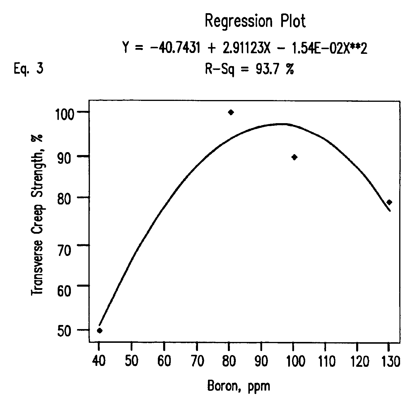
[0077]It has been found, according to the invention, that increasing the boron from about 30-50 ppm in the SC Rene N4 specification to no greater than 130 ppm boron, along with several changes in part configuration, including bucket shape, essentially eliminates casting cracks in large turbine buckets. The additional boron may create a “M5B3” phase where M is Ni or Ni5B3 eutectic phase in the grain boundaries and elsewhere within the alloy matrix (as determined by Auger Spectrometry and Microdiffraction analyses), and the melting properties of the alloy have been attributed to the presence of a “M5B3” boron phase. The presence of this eutectic phase lowers the incipient melting point (the point at which the metal starts to melt) from 2334° F. to 2301° F. (as determined by Differential Thermal Analysis (DTA)). Thus, after application of a 2320° F. heat treatment (normal for SC Rene N4), the DS alloys begin to melt at locations within the eutectic pools where the boron as Ni5B3 is con...
PUM
| Property | Measurement | Unit |
|---|---|---|
| Temperature | aaaaa | aaaaa |
| Temperature | aaaaa | aaaaa |
| Temperature | aaaaa | aaaaa |
Abstract
Description
Claims
Application Information