Laser microscope

a laser microscope and microscope technology, applied in the field of laser microscopes, can solve the problems of affecting the acquisition of spectral data, affecting the stability of spectral data, and affecting the accuracy of spectral data acquisition, so as to achieve the effect of minimizing the loss of light volume and stabilizing the spectral data

Inactive Publication Date: 2005-06-21
OLYMPUS CORP
View PDF7 Cites 41 Cited by
  • Summary
  • Abstract
  • Description
  • Claims
  • Application Information

AI Technical Summary

Benefits of technology

[0010]It is an object of the present invention to provide a laser microscope

Problems solved by technology

When a plurality of dichroic beam splitters is selectively used so as to be positioned on the optical path, however, fluorescence imaged at the end face of an optical fiber may be misaligned due to angle errors of respective dichroic beam splitters.
In view of these

Method used


Image

  • Laser microscope
  • Laser microscope
  • Laser microscope

Examples


first embodiment

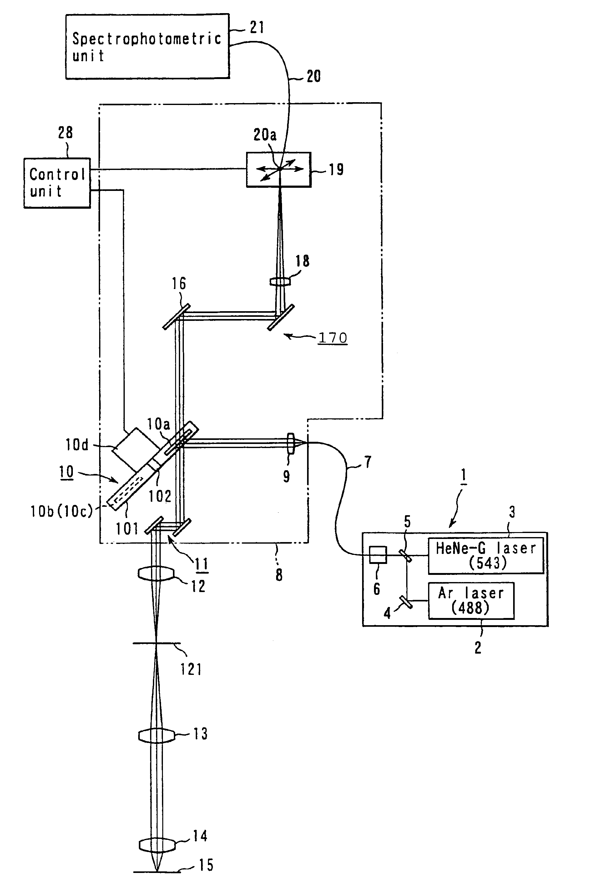
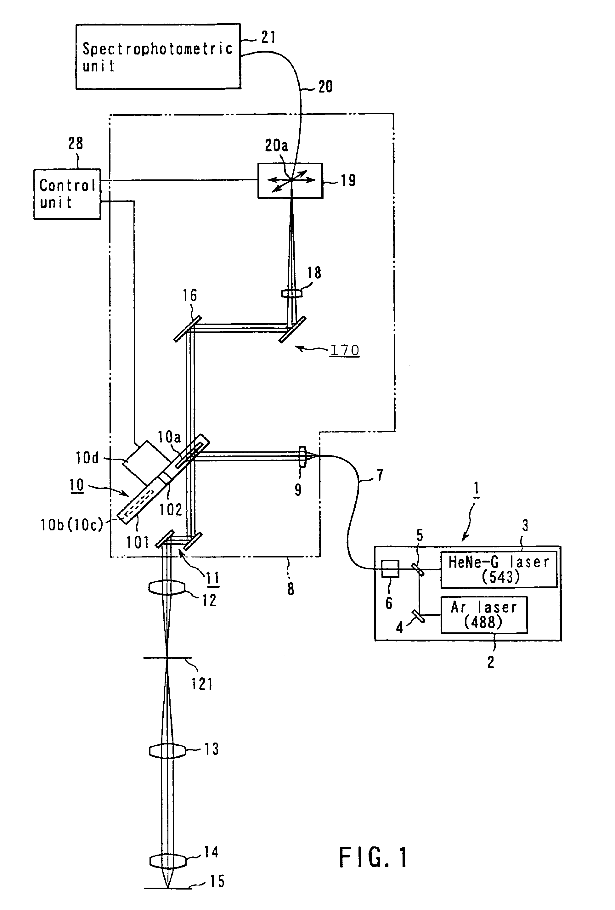
[0019]FIG. 1 shows a schematic configuration of a laser microscope according to the present invention. In FIG. 1, a laser unit 1 includes an Ar laser 2 and a green helium-neon (HeNe-G) laser 3 as laser light sources. The Ar laser 2 oscillates light of a 488 nm wavelength. The green helium-neon (HeNe-G) laser 3 oscillates light of a 543 nm wavelength. A mirror 4 is placed ahead of the Ar laser 2. A dichroic mirror 5 is placed ahead of the green helium-neon (HeNe-G) laser 3. The mirror 4 and the dichroic mirror 5 connect laser optical paths for the Ar laser 2 and the green helium-neon (HeNe-G) laser 3, synthesizing light of 488 nm and 543 nm wavelengths. On the laser optical path guided by the dichroic mirror 5, there is provided an acousto-optic tunable filter (hereafter referred to as an AOTF) for selecting the light of the 488 nm or 543 nm wavelength. The laser unit 1 connects with a scanner unit 8 via a single-mode fiber 7.

[0020]In the scanner unit 8, a collimating lens 9 is provi...

second embodiment

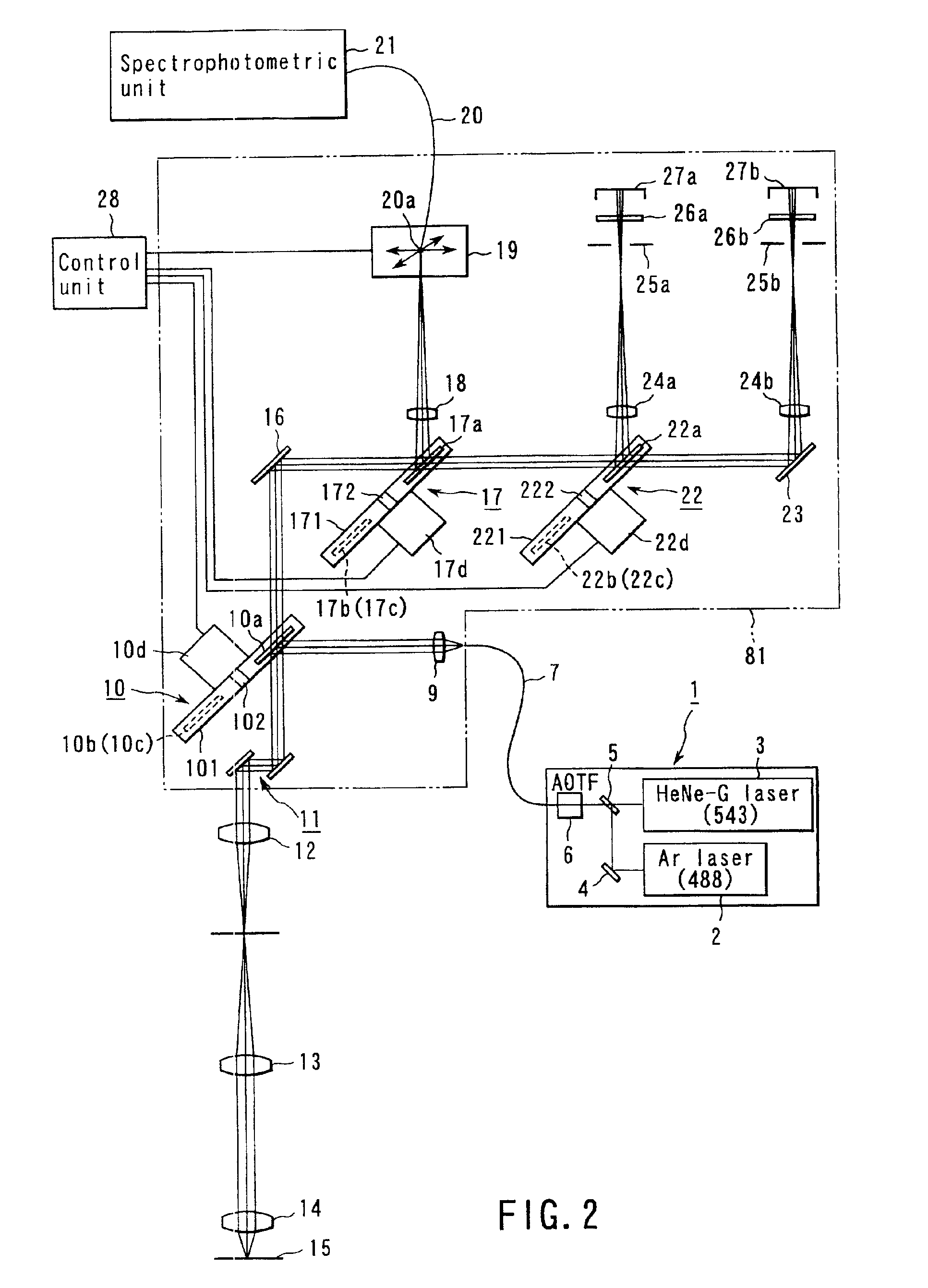
[0039]FIG. 2 shows a schematic configuration of a laser microscope according to the present invention. The mutually corresponding parts in FIGS. 2 and 1 are designated by the same reference numerals. The following describes the configuration in FIG. 2 with respect to specifics which differ from FIG. 1.

[0040]In FIG. 2, there are provided the reflective member unit 17, a dichroic mirror unit 22, and a reflecting mirror 23 on a reflected optical path for the reflecting mirror 16 in a scanner unit 81.

[0041]The reflective member unit 17 supports a mirror 17a, a dichroic mirror 17b, and a parallel-plate glass 17c (not shown). The reflective member unit 17 comprises a rotatable, disk-shaped turret 171. The mirror 17a, the dichroic mirror 17b, and the parallel-plate glass 17c are arranged concentrically with the turret 171. A rotating shaft 172 of a motor 17d is mounted at the center of the turret 171.

[0042]The mirror 17a reflects light of all wavelengths. The dichroic mirror 17b is used fo...

third embodiment

[0057]FIG. 3 shows a schematic configuration of a laser microscope according to the present invention. The mutually corresponding parts in FIGS. 3 and 2 are designated by the same reference numerals The following describes the configuration in FIG. 3 and respect to specifics which differ from FIG. 2.

[0058]In FIG. 3, the condensing lens 18 is arranged on a reflected optical path for the reflective member unit 17 in the scanner unit 82. An electric transfer mechanism 32 is arranged at an imaging position for the condensing lens 18. Like the electric transfer mechanism 19, the electric transfer mechanism 32 comprises, e.g., a motor-driven XY stage. This mechanism moves one end face 20a of the optical fiber 20 in the XY direction to position the center of the end face 20a to the imaging position for the condensing lens 18. The optical fiber 20 is led from the spectrophotometric unit 21.

[0059]A confocal pinhole 31 is arranged at a position which is immediately in front of the end face 20...


PUM


Abstract

A laser microscope according to the present invention comprises a laser light source which generates a laser beam, an optical path split portion which has a plurality of optical path split elements with different characteristics for separating the laser beam irradiated to a sample from the laser light source and light returned from the sample and includes a selection mechanism to switch these optical path split elements on an optical path, an imaging lens to converge light which is returned from the sample and is separated in the optical path split portion, a spectrophotometric detection unit which obtains spectral data of light from the sample, an optical fiber which guides light from the sample imaged by the imaging lens to the spectrophotometric detection unit, wherein an incident end face of the fiber is arranged to a position substantially conjugate to the sample, and a transfer mechanism which moves an incident end face of the optical fiber in a plane orthogonal to an optical axis of light incident on the optical fiber.

Description

CROSS-REFERENCE TO RELATED APPLICATIONS[0001]This application is based upon and claims the benefit of priority from the prior Japanese Patent Application No. 2001-070805, filed Mar. 13, 2001, the entire contents of which are incorporated herein by reference.BACKGROUND OF THE INVENTION[0002]1. Field of the Invention[0003]The present invention relates to a laser microscope having a spectrophotometric unit which obtains spectral data for light from a sample, especially for fluorescence.[0004]2. Description of the Background Art[0005]Conventionally, there is known a laser microscope which converges a laser beam onto a sample via an objective lens, incorporates light, e.g., fluorescence from the sample into a spectrophotometric unit via an optical fiber, and obtains spectral data for the fluorescence.[0006]This type of laser microscope is disclosed in Jpn. Pat. Appln. KOKAI Publication Nos. 5-142144 and 2000-56244. Especially, Jpn. Pat. Appln. KOKAI Publication No. 2000-56244 discloses a...

Claims


Application Information

Patent Timeline
IPC IPC(8): G02B21/00G02B21/06G01J3/02G01J3/00G01N21/64
CPCG02B21/06G02B21/002G01J3/0221
Inventor SASAKI, HIROSHI
Owner OLYMPUS CORP
Why Eureka
Try Eureka