Thermally matched fluid cooled power converter

a technology of fluid cooled power converter and power electronic device, which is applied in the direction of power conversion system, cooling/ventilation/heating modification, lighting and heating apparatus, etc., can solve the problems of difficult realization of solutions for reducing inductance, difficulty in appropriately placing power electronic devices, etc., and achieves the effect of improving performance, light weight and efficient configuration

Active Publication Date: 2005-06-21
ROCKWELL AUTOMATION TECH
View PDF66 Cites 60 Cited by
  • Summary
  • Abstract
  • Description
  • Claims
  • Application Information

AI Technical Summary

Benefits of technology

[0008]The present technique provides power electronics modules designed to respond to such needs. The technique makes use of novel packaging, thermal management, interconnect, and grounding shielding approaches which both improve performance, and offer smaller, lighter and more efficient configurations of the power electronic devices and their drive circuitry. The technique offers multiple facets for such packaging and thermal management which can be adapted to a variety of settings, including industrial power electronics applications, vehicular applications, and so forth. Many of the embodiments of the present technique permit utilization of standardized cells designed to be reconfigured into a number of optimum configurations matching key application requirements.

Problems solved by technology

While numerous constraints exist in such settings which differ from those of industrial settings, numerous problems and difficulties are shared in all such applications.
Where size and weight constraints force reductions in the packaging dimensions, difficulties arise in appropriately placing the power electronic devices, and drive and control circuitry associated with the devices to sufficiently remove heat generated during their operation.
Electrical and electronic constraints also impose difficulties on package design.
For example, reduction of inductance in the circuits and circuit layout is commonly a goal, while solutions for reducing inductance may be difficult to realize.
Finally, certain environments, such as vehicle environments, impose a wide range of difficult operating conditions, including large temperature spans, vibration and shock loading, and so forth.
A particular problem arising in power electronics circuitry, and particularly in converting circuitry arises from differential thermal expansion and contraction between various circuit components.
Because extremes in environmental and enclosure temperatures, significantly different rates of expansion and contraction may arise within the power electronics circuits and within supporting structures.
In such circumstances, delamination, deterioration, and malfunction can arise due to repeated thermal cycles and the consequent expansion and contraction.
A particular challenge arises in cooling such circuitry, while preventing the degradation of the packaging and circuitry due to the thermal expansion and contraction.

Method used


Image

  • Thermally matched fluid cooled power converter
  • Thermally matched fluid cooled power converter
  • Thermally matched fluid cooled power converter

Examples


Embodiment Construction

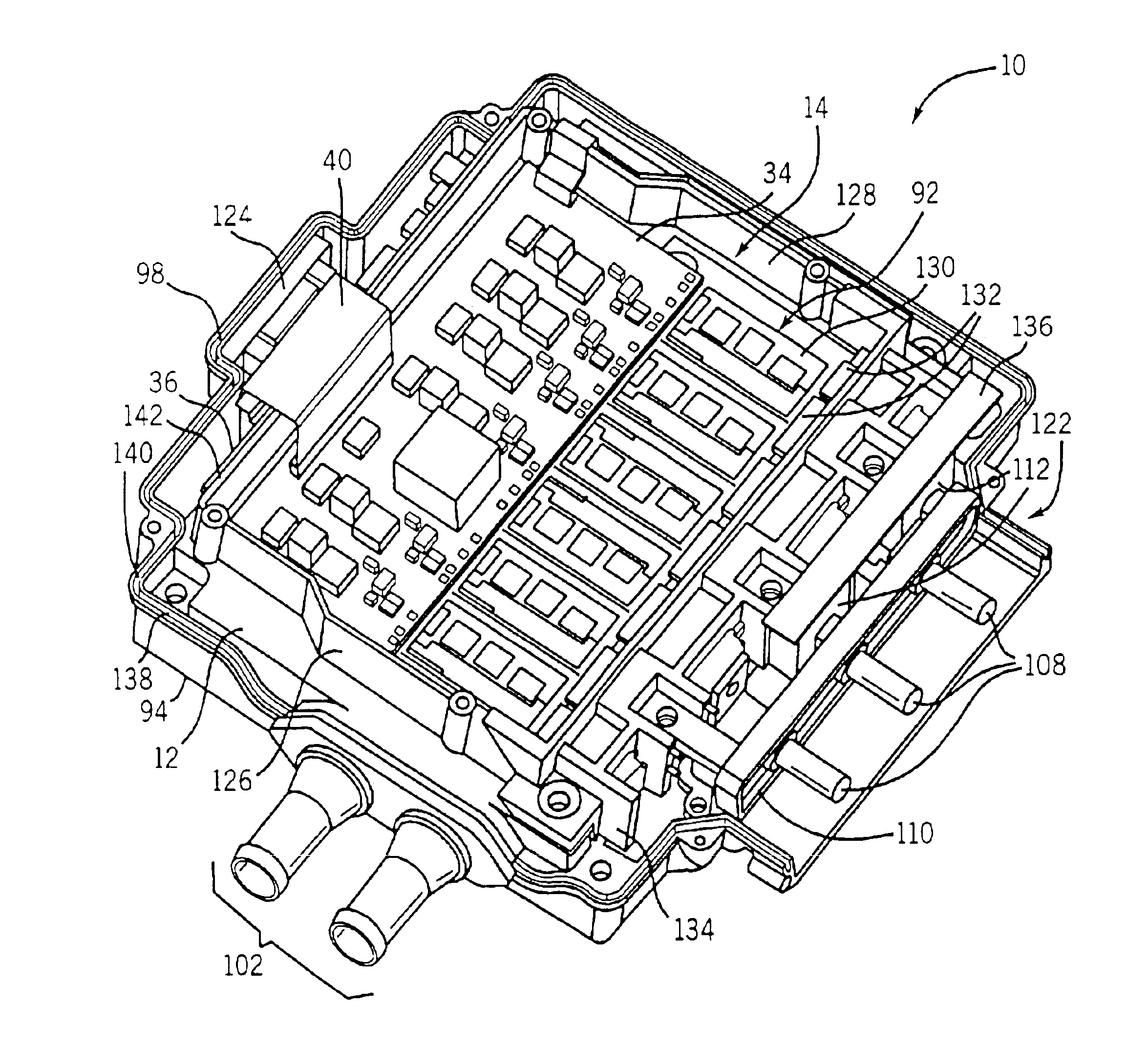
[0051]Before detailing specific embodiments of the inventive technique as presently contemplated, certain definitional notes are in order. Firstly, reference is made in the present disclosure to power devices and subassemblies incorporating such devices. Such devices may include a range of components, such as power electronic switches (e.g. IGBTs, FETs) of various power ratings. The devices may also include gate driver circuitry for such components, sensing and monitoring circuitry, protection circuitry, filtering circuitry, and so forth. The devices may be provided in the subassemblies in various groupings, both integrally and separate from supporting substrates and / or thermal expansion coefficient members and heat transfer elements. Reference is also made herein to energy storage and conditioning circuitry. Such circuitry may vary in composition depending upon the particular configuration of the associated power electronic devices and circuits. For example, in inverter drive appli...


PUM


Abstract

A thermal support may receive one or more power electronic circuits. The support may aid in removing heat from the circuits through fluid circulating through the support. Power electronic circuits are thermally matched, such as between component layers and between the circuits and the support. The support may form a shield from both external EMI/RFI and from interference generated by operation of the power electronic circuits. Features may be provided to permit and enhance connection of the circuitry to external circuitry, such as improved terminal configurations. Modular units may be assembled that may be coupled to electronic circuitry via plug-in arrangements or through interface with a backplane or similar mounting and interconnecting structures.

Description

CROSS-REFERENCE TO RELATED APPLICATIONS[0001]This application claims the benefit of U.S. Provisional Application No. 60 / 349,259, filed Jan. 16, 2002.GOVERNMENT LICENSE RIGHTS[0002]This invention was made with Government support under Cooperative Agreement No. DE-FC02-99EE50571 awarded by the Department of Energy. The Government has certain rights in this invention.BACKGROUND OF THE INVENTION[0003]The present technique relates to power electronic devices and their incorporation into modules and systems. More particularly, the technique relates to the configuration, packaging and thermal matching within of power electronic devices and supports within modular power converters.[0004]A wide array of applications are known for power electronic devices, such as power switches, transistors, and the like. For example, in industrial applications, silicon controlled rectifiers (SCRs), insulated gate bipolar transistors (IGBTs), field effect transistors (FETs), and so forth are used to provide ...

Claims


Application Information

Patent Timeline
Patent Type & Authority Patents(United States)
IPC IPC(8): H02M7/00H05K7/20H02M1/44
CPCH02M1/44H05K7/20927H02M7/003
Inventor RADOSEVICH, LAWRENCE D.KANNENBERG, DANIEL G.KAISHIAN, STEVEN C.BEIHOFF, BRUCE C.
Owner ROCKWELL AUTOMATION TECH
Why Eureka
Try Eureka