
Systems and methods for timing a linear data path element during signal-timing verification of an integrated circuit design

a linear data path and integrated circuit technology, applied in computer aided design, program control, instruments, etc., can solve the problems of ineffective use of available circuit area, clock uncertainty, and inability to identify signal timing problems,

Inactive Publication Date: 2005-06-21
BROADCOM INT PTE LTD
View PDF17 Cites 32 Cited by
  • Summary
  • Abstract
  • Description
  • Claims
  • Application Information

AI Technical Summary

Benefits of technology

[0015]Systems and methods of the present invention relate to verifying signal-timing relationships for signals that traverse linear data path structures of an integrated circuit. More specifically, systems and methods of the present invention verify that signals that are serially processed from element to element will behave as expected. The systems and methods of the present invention can be used to develop a confidence interval. A confidence interval is a period of time or buffer in addition to the minimum time during which a signal event is likely to occur. Thus, longer confidence intervals go hand in hand with greater probability that the integrated circuit will function as designed. The systems and methods of the invention account for clock signal propagation delays and transition time degradation for signals that traverse linear data structures within the integrated circuit.

Problems solved by technology

One of the more difficult aspects of VLSI circuit design deals with the problem of how to identify and resolve circuit failures due to signal timing problems.
Signal timing problems are often not identified until after each functional block designer has completed and integrated a specific functional block circuit design into a timing model.
One factor that affects signal timing success across the various functional blocks of a VLSI circuit design is clock uncertainty.
However, this approach requires a complete clock distribution structure for each functional block.
As a result, this approach can lead to inefficient use of available circuit area.
Not only will this approach adversely impact integrated circuit efficiency, the simple timing model suitable for signal paths supplied by the distributed clock signal represents an oversimplification when linear data path structures are introduced in the integrated circuit.
Because the overall signal processing delay for a clock signal that traverses each of the logic circuits or elements of the linear data path structure is cumulative and because the transition time degrades for a signal received at each successive circuit or element, the clock uncertainty model does not accurately reflect signal timing relationships for signal paths that originate and or terminate within a linear data path.
Moreover, static timing tools do not provide a mechanism to convey signal timing performance information for signals that traverse linear data path structures.

Method used


Image

  • Systems and methods for timing a linear data path element during signal-timing verification of an integrated circuit design
  • Systems and methods for timing a linear data path element during signal-timing verification of an integrated circuit design
  • Systems and methods for timing a linear data path element during signal-timing verification of an integrated circuit design

Examples


Embodiment Construction

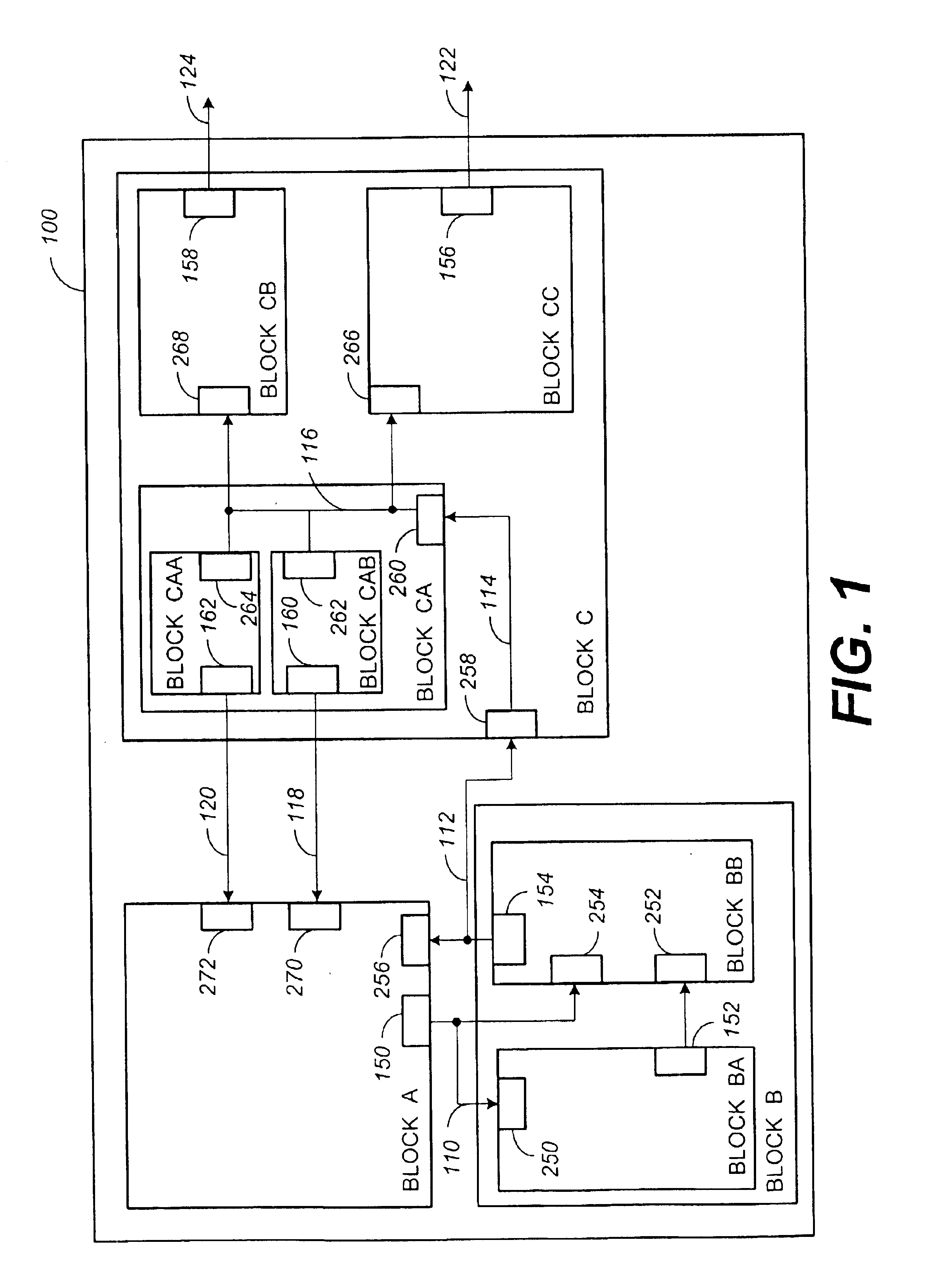
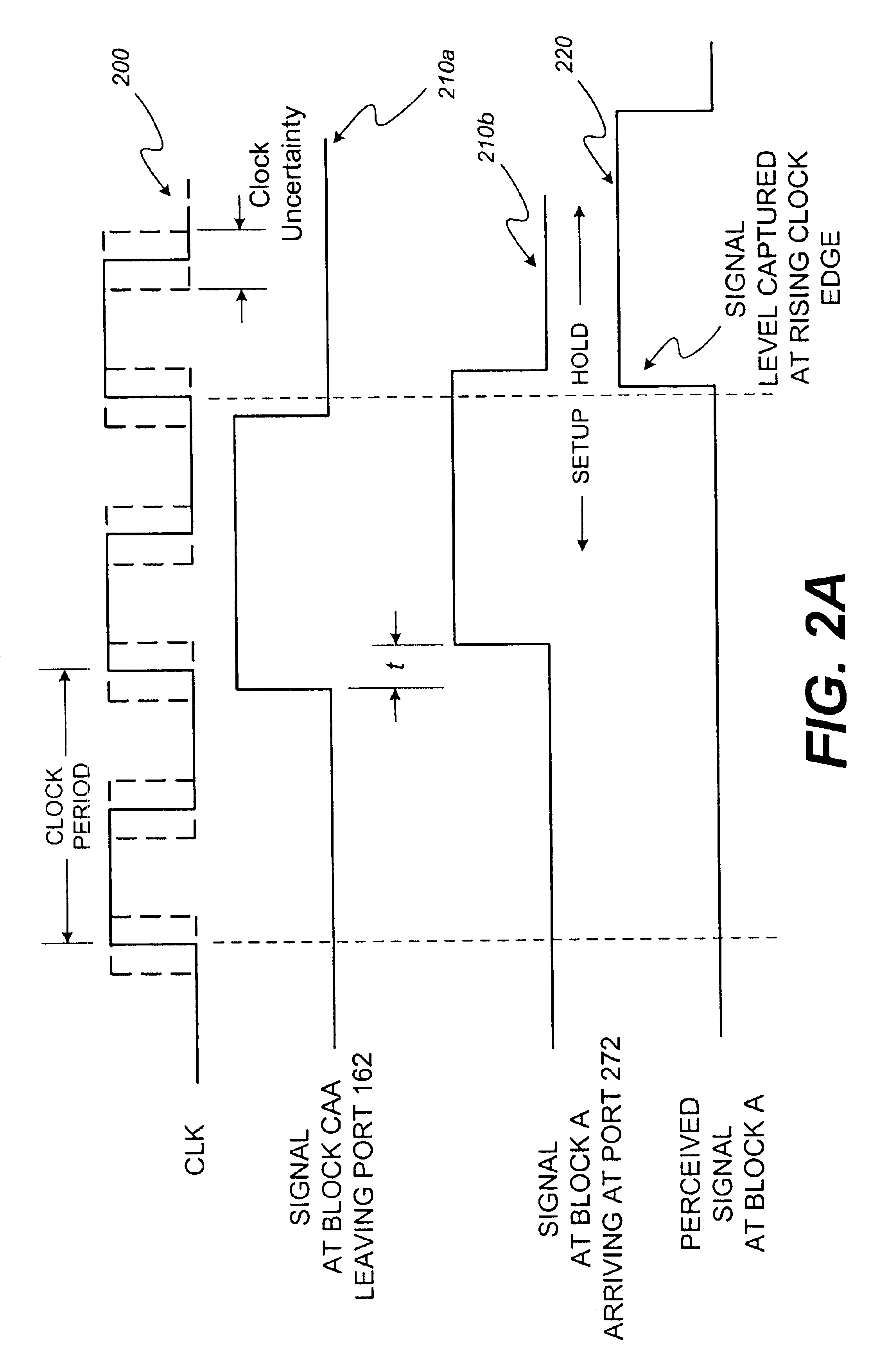
[0028]The block diagrams and schematic presented in FIGS. 1 and 2 are provided to illustrate and describe aspects of computer aided circuit design pertinent to the present invention. In this regard, FIG. 1 shows that an integrated circuit may be arranged and modeled with a plurality of separately defined functional blocks arranged and coupled in a hierarchical fashion across the integrated circuit. FIG. 2 illustrates the importance of tightly coordinating the relative timing between clock and data signals across an integrated circuit.

[0029]FIG. 1 is a block diagram illustrating an embodiment of an integrated circuit representation 100 that may be generated by a computer aided design tool. The integrated circuit representation 100 illustrated in FIG. 1 is grossly oversimplified for ease of illustration and discussion of aspects pertinent to the scope of the invention. It should be understood that VLSI circuits may contain tens to hundreds of millions of transistors and other various ...


PUM


Abstract

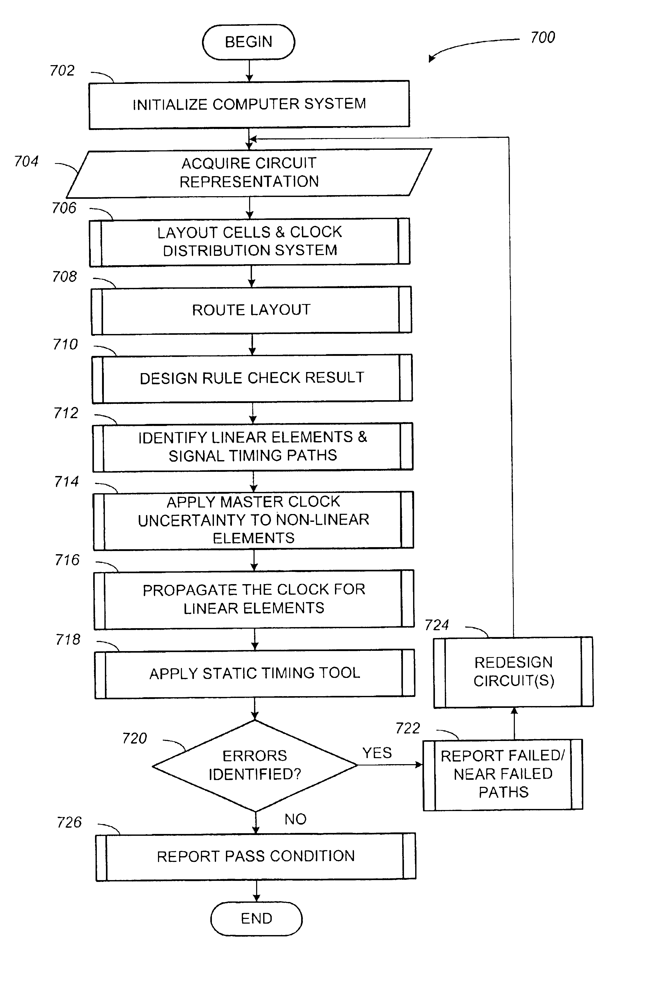
Systems and methods for timing a linear data path element within an integrated circuit design are provided. A representative system includes a computer and a memory element associated with the computer. The computer includes logic for receiving information describing the integrated circuit design. The integrated circuit design includes a description of a signal-timing path and the clock distribution system across the integrated circuit. The memory is configured with executable steps to generate a model of a signal that traverses a signal-timing path that is coupled to a linear element. The model includes a mechanism for simulating clock signal operation over a plurality of clock distribution structure types. A representative method includes the following steps: acquiring circuit information; identifying a signal path within the circuit information; recognizing when the signal-timing path is coupled to a linear element; associating a clock uncertainty with the clock signal; determining a confidence interval for the signal-timing path responsive to the recognizing step, wherein the clock signal is propagated along the signal-timing path; and associating the confidence interval with the signal-timing path.

Description

BACKGROUND OF THE INVENTION[0001]1. Technical Field[0002]The present invention generally relates to computer aided integrated circuit design systems, and more particularly to systems and methods for accurately verifying signal timing for signal paths in an integrated circuit.[0003]2. Description of the Related Art[0004]Integrated circuits are electrical circuits that arrange transistors, resistors, capacitors, and other components on a single semiconductor die or substrate, upon which the various components are interconnected to perform a variety of functions. Typical examples of integrated circuits include, for example, microprocessors, programmable-logic devices (PLDs), electrically-erasable-programmable-read-only memory devices (EEPROMs), random-access-memory (RAM) devices, operational amplifiers, voltage regulators, etc.[0005]Often, circuit designs are simulated by computer to verify functionality and timing to ensure that performance goals will be satisfied. Design and circuit ...

Claims


Application Information

Patent Timeline
Patent Type & Authority Patents(United States)
IPC IPC(8): G06F17/50
CPCG06F17/5031G06F30/3312
Inventor MIELKE, DAVID JAMESMEIER, VICTORIA
Owner BROADCOM INT PTE LTD
Learn More