ALD apparatus and method

a technology of ald apparatus and method, applied in the direction of chemical vapor deposition coating, transportation and packaging, coating, etc., can solve the problems of reducing throughput, preventing cost-effective implementation of ald systems and methods for manufacturing semiconductor devices and other devices, and cvd techniques that exceed the limits of conventional cvd techniques, etc., to achieve the effect of further improving throughput and material utilization

Inactive Publication Date: 2005-06-28
SUNDEW TECH
View PDF44 Cites 421 Cited by
  • Summary
  • Abstract
  • Description
  • Claims
  • Application Information

AI Technical Summary

Benefits of technology

[0057]In some embodiments, pressure in the process chamber (or ALD chamber) is maintained substantially constant during synchronous flow-draw modulation. In other embodiments in accordance with the invention, throughput and material utilization are further improved by conducting one or more chemical-dosage stages at higher pressures. For example, in some embodiments, the pressure during purge is maintained in a range of about from 30 mTorr to 100 mtorr, while ALD-pressure during chemical dosage is maintained in a range from 200 mtorr to 1000 mTorr.

Problems solved by technology

Nevertheless, as device density increases and device geometry becomes more complicated in integrated circuit devices, the need for thinner films with superior conformal coating properties has approached the limits of conventional CVD techniques and new techniques are needed.
Multiple technical challenges have so far prevented cost-effective implementation of ALD systems and methods for manufacturing of semiconductor devices and other devices.
Nevertheless, this necessarily degrades throughput since cycle times increase correspondingly.
Existing ALD apparatuses have struggled with the trade-off between the need to shorten reaction times and improve chemical utilization efficiency, and on the other hand, the need to minimize purge-gas 
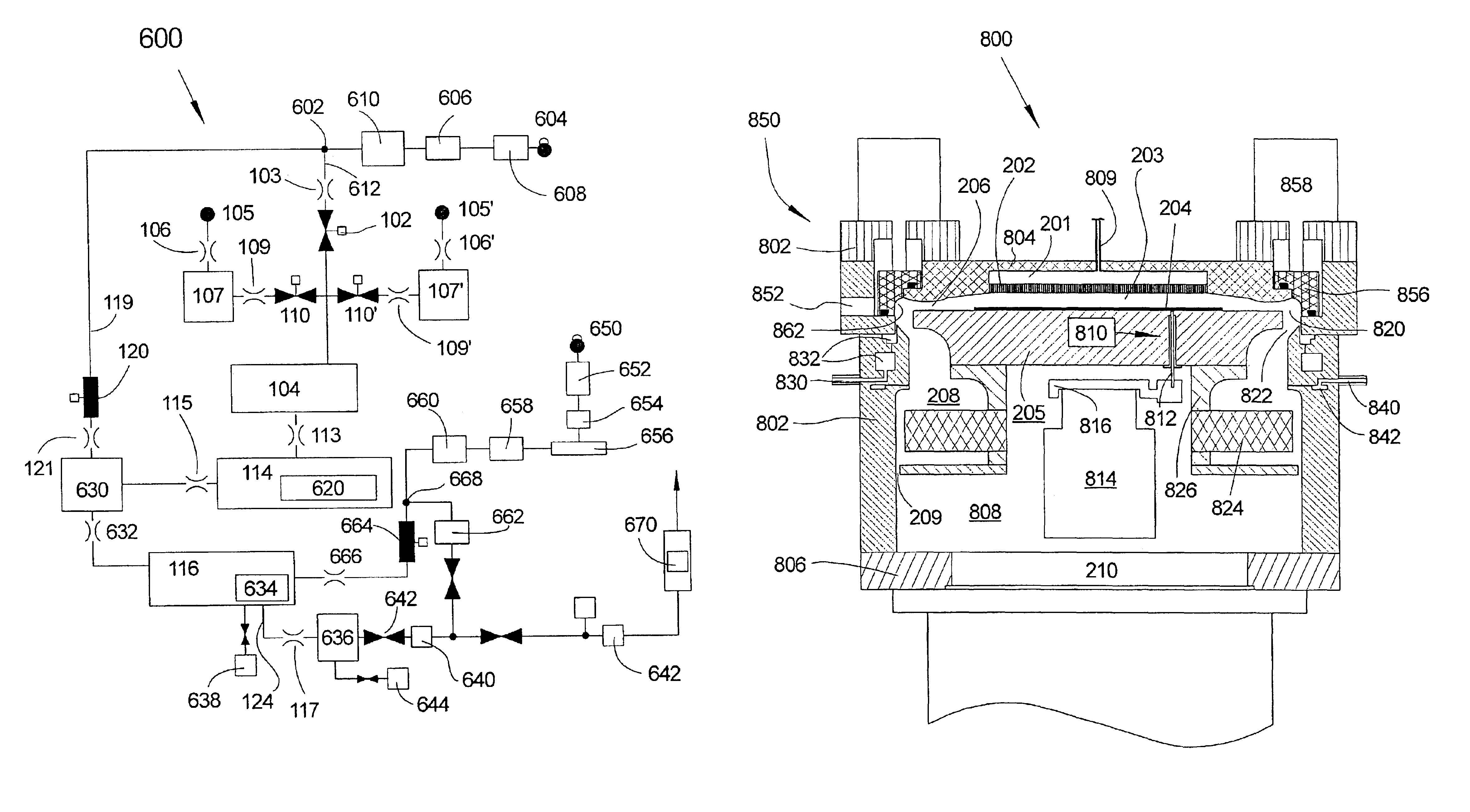
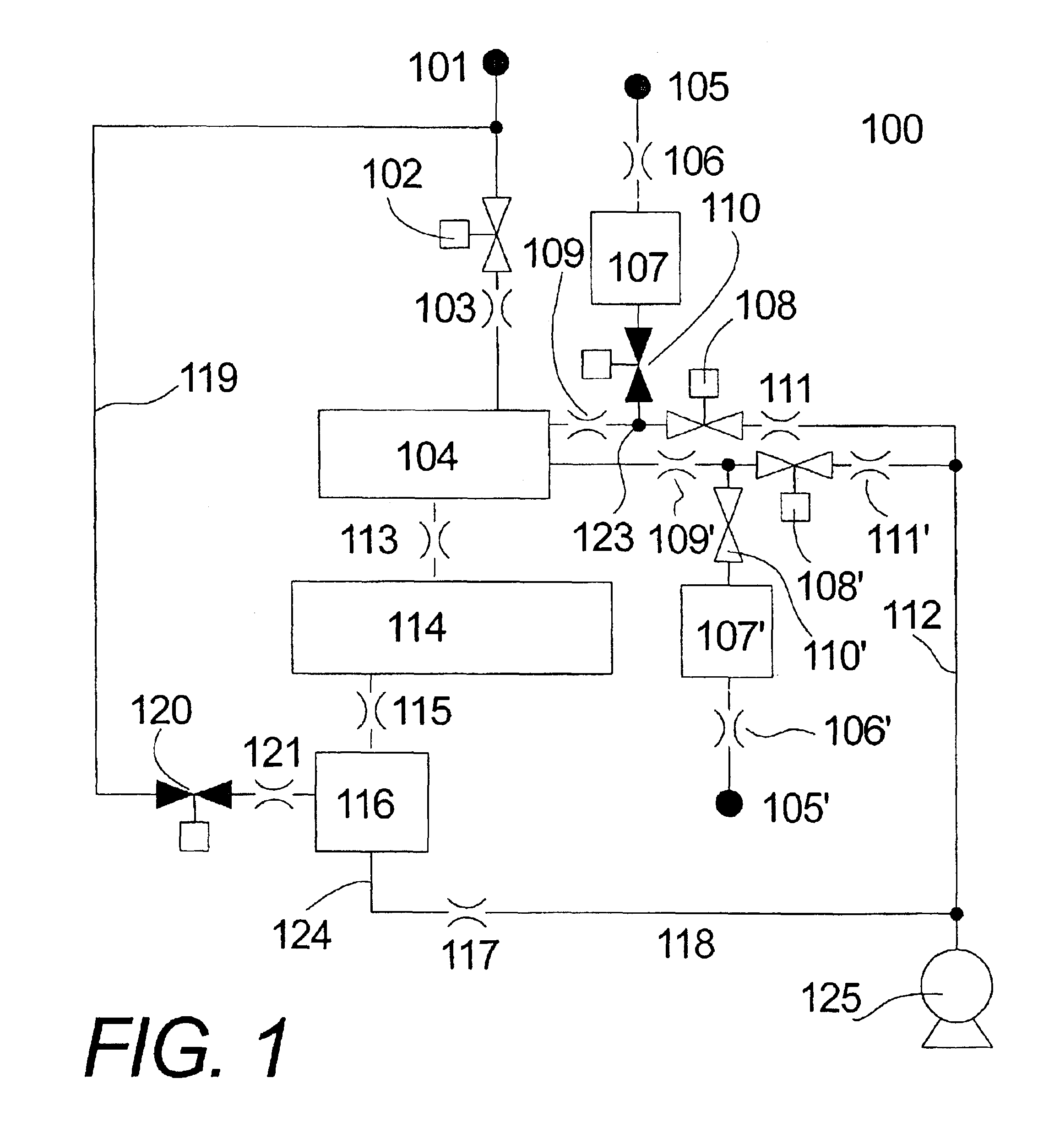
residence and chemical removal times. Certain ALD systems of the prior art contain chemical delivery manifolds using synchronized actuation of multiple valves.
In such systems, satisfactory elimination of flow excursions is impossible because valve actuation with perfect synchronization is itself practically impossible.
As a result, the inevitable flow excursions are notorious for generating backflow of gas that leads to adverse chemical mixing.
As a conventional ALD apparatus is utilized, “memory” effects tend to reduce the efficiency of the ALD reactor.
This phenomenon tends to increase the residence time of trace amounts of chemicals in the ALD reactor.
As a result, memory effects tend to increase the purge-time required for removal of chemicals.
Film growth on chamber walls deteriorates performance of the ALD apparatus to the extent that the growth of film produces an increased surface area on the walls of the ALD chamber.
An increase in surface area may result from the growth of inferior porous film deposits.
The adverse coexistence could only be avoided by purging a substantially larger volume, thereby significantly sacrificing throughput of the ALD system.
Typically, ALD precursors coexisting in a chamber space tend to produce inferior films.
As a result, throughput-optimized ALD systems suffer from the tendency to grow inferior solid deposits in the space immediately downstream from the ALD space.
Inferior film growth becomes increasingly worse because the inferior films present increased surface area, which enhances precursor coexistence, thereby aggravating the problem.
Since some of the chemicals proximately downstream from the ALD space return back into the ALD reaction space (e.g., by diffusion), ALD performance deteriorates.
In addition, inferior deposition of particles on the substrate results.
Accordingly, conventional ALD systems operated at peak throughput are doomed to rapid buildup of contamination and rapid degradation of ALD performance.
However, considerations of safety and the need to seamlessly integrate abatement into an optimized ALD system considerably restrict the practical feasibility and cost effectiveness of most abatement techniques.
Certain properties of typical ALD precursor combinations make the design of hot trap process conditions specific and difficult to control; for example, the precursors TMA and H2O that are used to deposit Al2O3 ALD films.
Accordingly, it is difficult to avoid growth of inferior Al(OH)3 deposits.
Likewise, close inspection of other ALD precursor systems reveal that typically Ahy-type precursors must be excessively dosed, thereby creating problematic inferior deposits such as oxychlorides and amine salts.
Accordingly, it is a typical observation that, unfortunately, ALD precursor combinations can deposit exceptional quality ALD films but, if allowed to react under CVD conditions, under typical exhaust conditions where the concentration of Ahy precursor is high, create inferior films.
This potential accumulation of H2O would be aggravated if the deposition of inferior films became excessive, and diffusion of accumulated H2O back into the reaction space could lead to deteriorated ALD performance.
Accordingly, hot traps, such as the one described in U.S. Application Publication 2002 / 0187084, are not a good choice for ALD abatement unless means are provided to control accumulation of ALD precursors, typically the ones that must be excessively used.
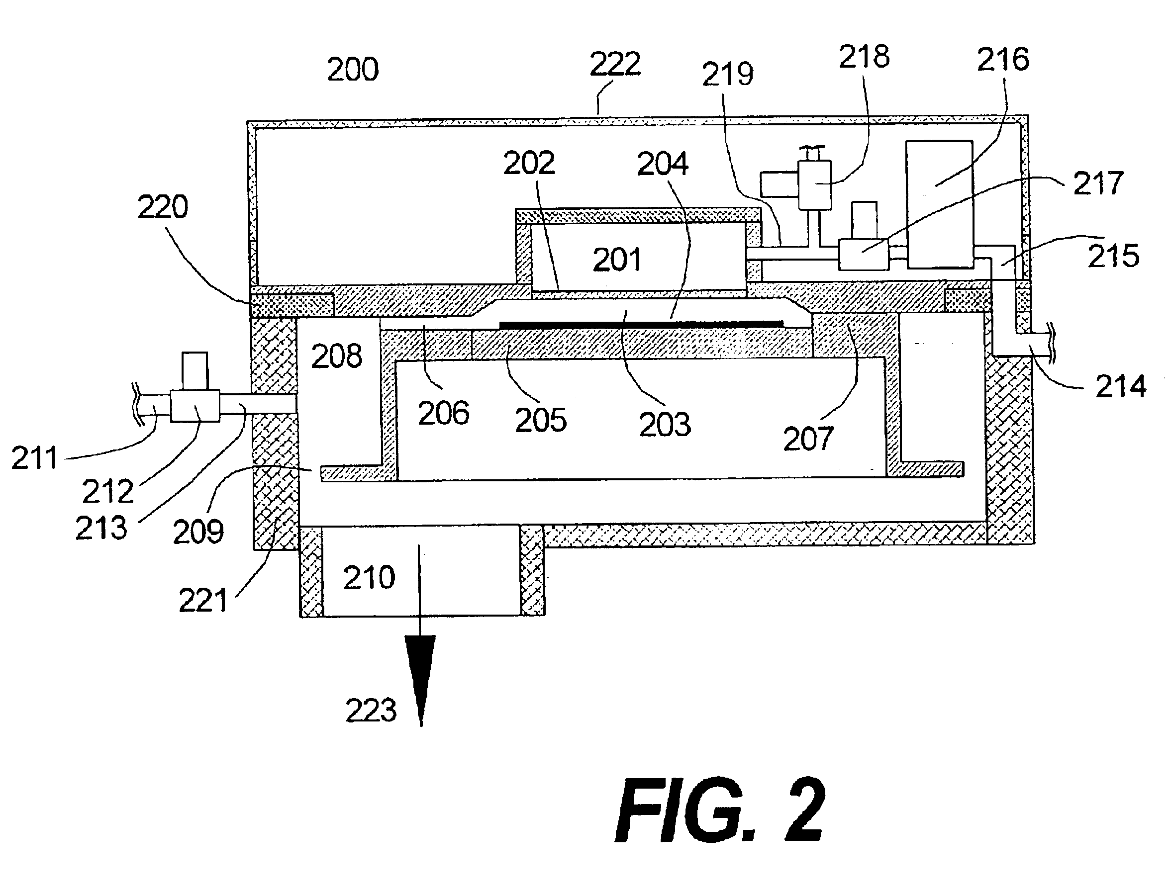
In existing CVD, PECVD, and ALD systems, gas entrapment and gas-flow disturbances in a reaction chamber, and resulting gas-flow and gas-pressure nonuniformities at the substrate surface, commonly cause adverse nonuniformities in the thickness and other characteristics of the deposited thin film.
However, gas entrapment and gas-flow disturbances often severely and adversely impact the effectiveness of purge steps.
For example, the “dead-leg” space associated with the wafer transport channel in the wall of a single wafer processing chamber is a known problem in the art of wafer processing such as CVD, etch, ALD and PVD.
In particular, effective ALD purge of this space typically is impossible.
Both of these prior art solutions and other prior art solutions are not well-suited to resolve the problems associated with substrate transport mechanisms in ALD systems.

Method used


Image

  • ALD apparatus and method
  • ALD apparatus and method
  • ALD apparatus and method

Examples


example 1

[0171]An exemplary SMFD ALD system corresponding to system 600 of FIG. 12 was designed and constructed for conducting SMFD ALD in accordance with the invention to deposit Al2O3 using the reactant gases trimethylaluminum (“TMA”) and H2O. Descriptions of the various components, identified using reference numerals of FIG. 12, of the exemplary system are included in Table 2, below, in which appropriate physical design, dimensions, and functional characteristics are entered. Preferred values of process parameters set, measured, or calculated during operation of the exemplary system are listed in Table 3. Definitions and explanatory notes, listed below Table 3, are referenced in Tables 2 and 3 by numbers (1) through (11).

[0172]

TABLE 2Component Ref. No.DesignPreferred Value608 MFM (1)MKS0 sccm-2000 sccm606 Pressure controllerMKS 640A0 Torr-1000 Torr610 Gas preheat boxAluminum Container1500 cc103 FRELong Tube0.052 liter / sec (4)106 FRELong Tube0.030 liter / sec (5)106′ FRELong Tube0.010 liter / ...


PUM

PropertyMeasurementUnit
aspect ratiosaaaaaaaaaa
thicknessaaaaaaaaaa
pressureaaaaaaaaaa

Abstract

An apparatus and method for atomic layer deposition with improved efficiency of both chemical dose and purge is presented. The apparatus includes an integrated equipment and procedure for chamber maintenance.

Description

RELATED APPLICATIONS[0001]This application claims the benefit of U.S. Provisional Patent Application Ser. No. 60 / 349,634 filed Jan. 17, 2002.BACKGROUND OF THE INVENTION[0002]1. Field of the Invention[0003]This invention relates to the field of atomic layer deposition (“ALD”), and more particularly to systems and methods for performing ALD with high throughput and low cost.[0004]2. Description of Prior Art[0005]Thin film deposition is commonly practiced in the fabrication of semiconductor devices and many other useful devices. Well-known techniques of chemical vapor deposition (“CVD”) utilize chemically reactive molecules that react in a reaction chamber to deposit a desired film on a substrate. Molecular precursors useful for CVD applications comprise elemental (atomic) constituents of the film to be deposited and typically additional elements. CVD precursors are volatile molecules that can be practically delivered, in the gas phase, to react at the substrate.[0006]Conventional CVD ...

Claims


Application Information

Patent Timeline
Patent Type & Authority Patents(United States)
IPC IPC(8): C23C16/56C23C16/44C23C16/455H01L21/687H01L21/67H01L21/00H01L21/31
CPCC23C16/4412C23C16/45544C23C16/45557C23C16/45561H01L21/68785C23C16/56H01L21/67126H01L21/6719C23C16/45565Y10T137/0396H01L21/20
Inventor SNEH, OFER
Owner SUNDEW TECH
Why Eureka
Try Eureka