Wavefront phase sensors using optically or electrically controlled phase spatial light modulators

Inactive Publication Date: 2005-06-28
US SEC THE ARMY THE
View PDF3 Cites 44 Cited by
  • Summary
  • Abstract
  • Description
  • Claims
  • Application Information

AI Technical Summary

Benefits of technology

[0009]Using a phase SLM, for example instead of the Zernike phase plate discussed above, provides considerable performance improvement including significantly reduced sensitivity to misalignments and wavefront tilts. It has been demonstrated mathematically that the conventional Zernike filter wavefront sensor, as well as the wavefront sensor described here, can be used in high-resolution direct adaptive-optic feedback systems; i.e., feedback systems that can be implemented in a parallel, distributed fashion without the complicated and time-consuming wavefront reconstruction calculations normally used in current adaptive optic wavefront control system architectures.
[0010]The direct adaptive optic feedback system approach is capable of high-resolution real-time correction of atmospheric turbu

Problems solved by technology

Typically the resolution of such systems is rather low.
Such resolution is difficult to, achieve with traditional wavefront sensors used in adaptive optics: shearing interferometers, Shack-Hartmann sensors, curvature sensors, etc.
Time-consuming calculations are also the principal obstacle for wavefront sensors based on focal plane techniques: phase retrieval from a set of pupil and focal plane intensity distributions, phase diversity, or Schlieren techniques.
For these methods, the dependence of the wavefront sensor output intensity (sensor output image) on phase is nonlinear, and phase reconstruction requires the solution of rather complicated inverse problems.
Hig

Method used


Image

  • Wavefront phase sensors using optically or electrically controlled phase spatial light modulators
  • Wavefront phase sensors using optically or electrically controlled phase spatial light modulators
  • Wavefront phase sensors using optically or electrically controlled phase spatial light modulators

Examples


Example

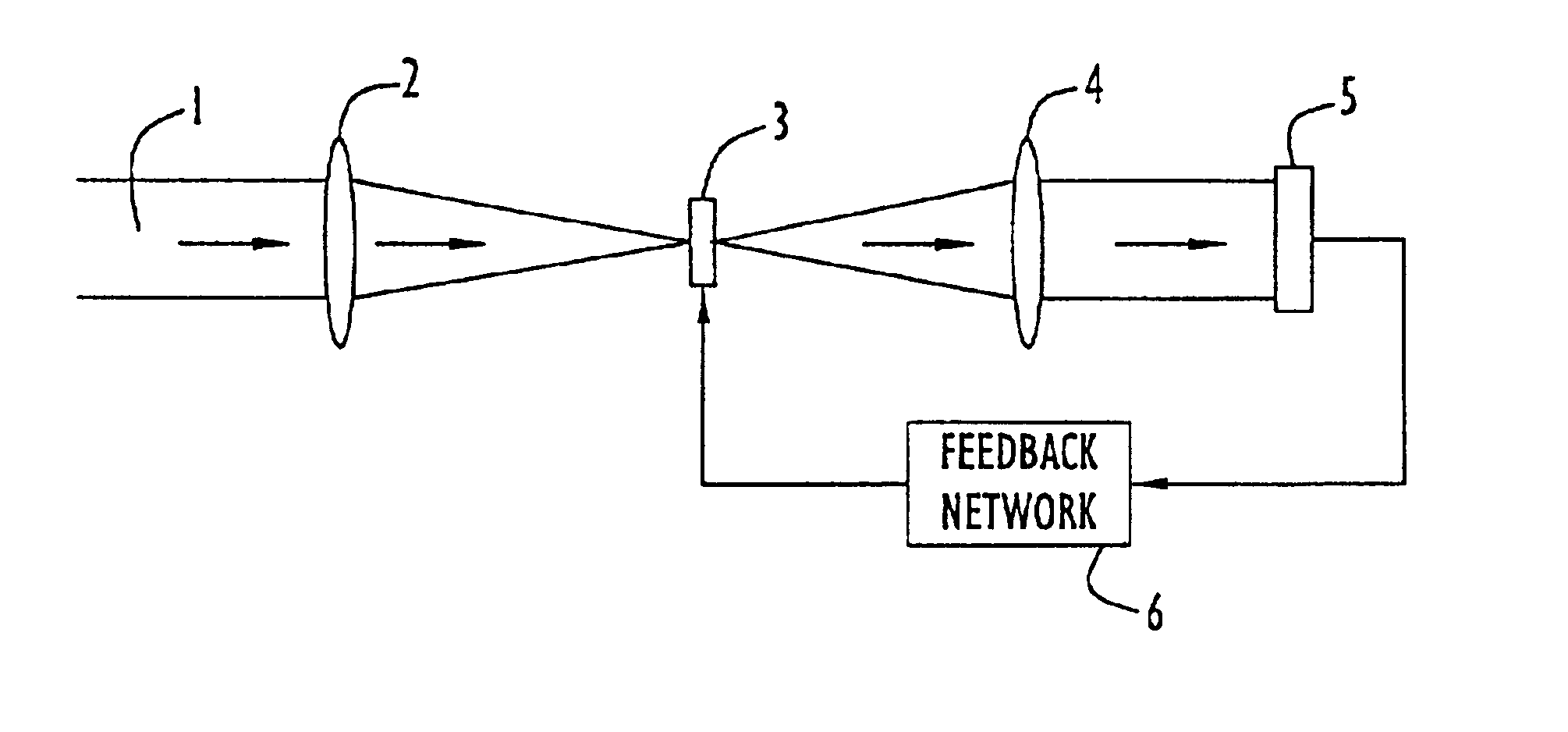
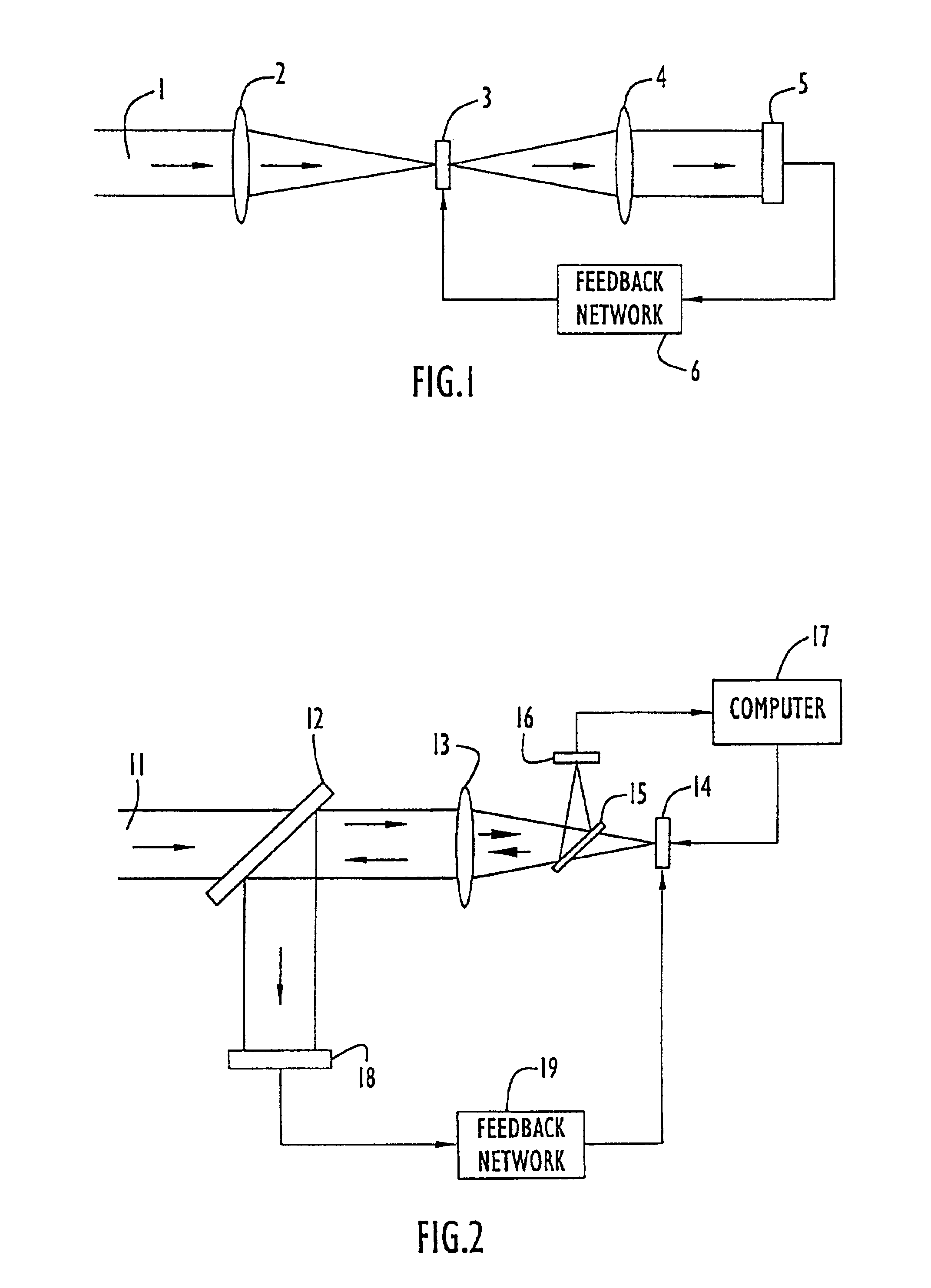
[0020]FIG. 1 shows a wavefront sensor based on a liquid crystal (LC) optically controlled phase SLM. A light beam 1 enters the system and is focused by lens 2 onto the LC optically controlled phase SLM 3: The SLM 3 responds to the optical intensity distribution incident upon it by producing a corresponding index of refraction (or birefringence) distribution that affects the light passing through the SLM. Lenses 2 and 4 are used in the usual manner for Fourier-domain filtering with SLM 3 serving as the Fourier-domain filter. The photodetector array 5 measures the output beam intensity distribution. If the SLM has an electrical input that controls its overall optical sensitivity (i.e., slope of the index of refraction change versus incident optical intensity curve) then this electrical input can optionally be adjusted to improve the output image contrast with the electronic feedback network 6 that uses an input signal from the photodetector array 5.

[0021]FIG. 2 shows a wavefront senso...


PUM


Abstract

Systems for optical wavefront sensing and control based on a phase contrast Fourier domain filtering technique. Optically or electronically controlled phase spatial light modulators (SLM) are used as the Fourier domain filter. A direct adaptive-optic feedback system using the optical wavefront sensing systems. A differential Zernike filter is also disclosed.

Description

STATEMENT OF GOVERNMENT INTEREST[0001]The invention described herein may be manufactured and used by or for the Government of the States of America for government purposes without the payment of any royalties therefor.FIELD OF THE INVENTION[0002]The present invention describes a system for wavefront sensing and control based on phase-contrast techniques using an optically or electronically controlled phase spatial light modulator. It also describes a methodology for wavefront sensing and control using this system.BACKGROUND OF THE INVENTION[0003]In the prior art, there are many well-known systems and techniques for wavefront sensing and wavefront phase distortion suppression. Typically the resolution of such systems is rather low. However, the situation is rapidly changing with the upcoming new generation of wavefront phase compensation hardware: liquid crystal and micro-electromechanical system (MEMS) phase spatial light modulators (SLMs) having on the order of 104 to 106 elements....

Claims


Application Information

Patent Timeline
IPC IPC(8): G02B26/06G02B26/00G01J9/00
CPCG02B26/06G01J9/00
Inventor VORONTSOV, MIKHAIL A.JUSTH, ERIC W.BERESNEV, LEONID I.KRISHNAPRASAD, PERINKULAMRICKLIN, JENNIFER C.
Owner US SEC THE ARMY THE
Why Eureka
Try Eureka