Rotating shaft apparatus

a technology of rotating shafts and rotating shafts, which is applied in the direction of crankshafts, bearing cooling, manufacturing tools, etc., can solve the problems of shortening the life of the bearings supporting the shaft, affecting the rotation speed of the crankshaft, so as to ensure the rigidity required, reduce heat generation, and be suitable for high-speed rotation

Inactive Publication Date: 2005-07-05
MAKINO MILLING MASCH CO LTD
View PDF17 Cites 32 Cited by
  • Summary
  • Abstract
  • Description
  • Claims
  • Application Information

AI Technical Summary

Benefits of technology

[0027]The front side bearing comprises a cylindrical roller bearing or a radial ball bearing which can bear a high radial load and the rear side bearing comprises a pair of angular ball bearings for receiving the radial and thrust loads. Therefore, the invention provides a rotating shaft apparatus which ensures the rigidity required of rotating shaft apparatuses, reduces the heat generation, and is suitable for high speed rotation. Further, according to the invention, the diameter of the shaft can be reduced to reduce its weight, which allows rapid control of the rotational speed of the shaft. According to the invention, because angular bearings are disposed at the smaller diameter portion of the shaft, relatively small angular bearings can be used to reduce the size of the rotating shaft apparatus and the production cost thereof. Further, according to the invention, the spinning motions of the angular ball bearings are reduced and therefore, the heat generation is also reduced. Therefore, a rotating shaft apparatus which is improved to increase its durability, reliability and rotational speed with relatively high DN value is realized.
[0028]The cooling of the shaft and the housing allows the thermal deformation in the shaft and the housing to be reduced. Therefore, a rotating shaft apparatus which can rotate at a high speed with high precision is realized.
[0029]According to the invention, the temperatures of the inner and outer races of the bearing can be directly detected and, on the basis of the detection results, the coolant supplied into the cooling passages in the shaft and the housing is controlled. Therefore, the coolant temperature can be precisely controlled. This allows the control of the internal pressure of the bearing, rotationally supporting the shaft, within an appropriate range, which reduces the heat generation due to the friction between the inner race, the outer race and the rolling elements to prevent the damage to the bearing when heat is generated during high speed rotation of the shaft. Therefore, the shaft can rotate at high speed because the heat generated in the bearing is reduced.
[0030]By lowering the temperature of the inner race of the bearing to lower than that of the outer race, the pressure on the rolling elements to the outer race, due to the thermal expansion, is reduced. This allows an appropriate internal pressure of the bearing and reduces the heat generation, due to the friction, between the outer race and the rolling elements of the bearing, which prevents damage to the bearing.
[0031]According to the invention, by providing the shaft with shaft cooling means and by providing the housing with motor cooling means and housing cooling means, the motor which generates much heat and the housing can be effectively cooled by the coolant supplied into the shaft, the motor and the housing through separate systems. Further, the shaft and the housing can be cooled separately from each other. Therefore, a precise rotating shaft apparatus is realized by reducing the thermal deformations in the shaft and in the housing.

Problems solved by technology

The higher the DN value of a shaft, the shorter the life of the bearings supporting the shaft becomes and, therefore, expensive bearings are required.
Particularly, in an angular ball bearing, contacting angles are defined between the balls and the inner and outer races, which results in spinning motions of the balls and slippage of balls relative to the inner and outer races, which further results in rupturing the lubricating oil film.
According to the second prior art, although the spindle is rotatably supported at the tail end portion by the back-to-back angular bearings, the spindle is formed with a constant diameter in the longitudinal direction, and therefore there is a problem, the same as in the first prior art, in connection with the increase in DN value accompanied with the increase in the rotational speed and the diameter of the shaft.
In such a case, if the housing is too cool, excessive internal pressure is applied to the rolling elements disposed between the inner and outer races, because the outer race cannot thermally expand.
Therefore, the internal race and the rolling elements are urged to the outer race so that the heat generation due to the friction between the inner race, the outer race and the rolling elements is increased, which results in damage to the bearing.
Therefore, a cooling condition of the housing cannot be clearly obtained and optimal control of the temperatures of the spindle and the housing cannot be conducted.
Therefore, according to the configuration of the third prior art, there is a problem that an optimal control of the temperatures of the inner and outer races of the bearings, attached to the spindle and the housing, respectively, cannot be conducted.
However, according to the fourth prior art, the temperatures of the inner and outer races are not measured and, therefore, the heat generated by the friction between the inner race, the outer race and the rolling elements cannot be eliminated, which may result in seizure of the bearing.
Therefore, the temperature of the heat generating portion in the bearing cannot be precisely detected because the sensors do not detect the temperatures of the inner and outer races of the bearing.
However, the stator cannot be sufficiently cooled by this configuration, and the heated lubricating liquid acts as a thermal medium heating the housing.

Method used


Image

  • Rotating shaft apparatus
  • Rotating shaft apparatus
  • Rotating shaft apparatus

Examples


Embodiment Construction

[0037]With reference to the drawings, a preferred embodiment of the invention will be described below. In this connection, in the embodiment described below, a spindle apparatus of a machine tool is described as an example of the rotating shaft apparatus.

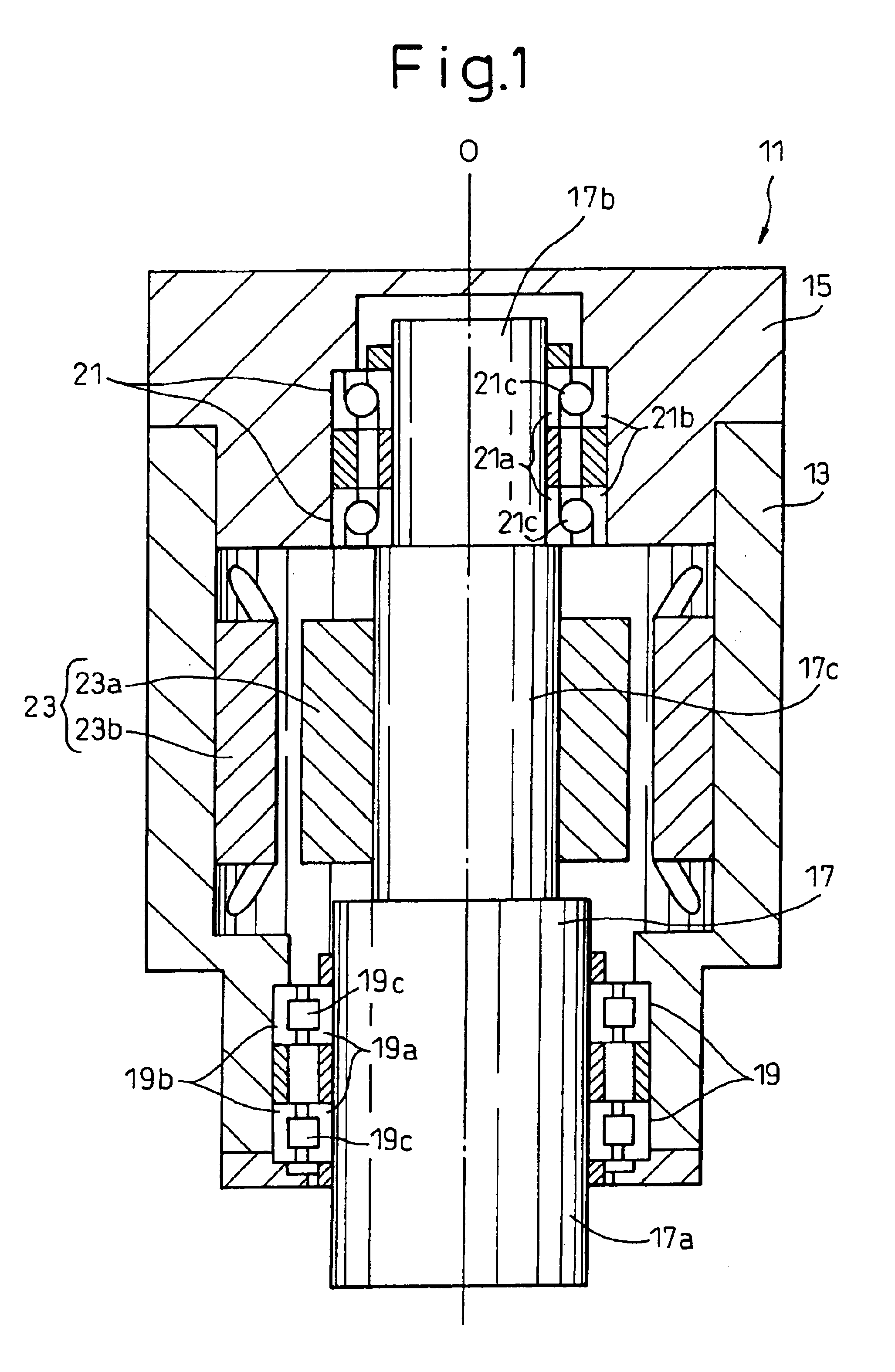
[0038]With reference to FIG. 1, a rotating shaft apparatus 11 comprises a shaft 17 rotatably supported by bearings 19 and 21 within a housing 13 and 15. The housing 13 and 15 has a housing body 13 and a rear cover 15 for closing the rear open end of the housing body 13. The shaft 17 has a front end portion 17a, a rear end portion 17b opposite to the front end portion 17a and an intermediate potion 17c between the front and rear end portions 17a and 17b. A functional member such as a tool (not shown) of the machine tool is attached to the front end portion 17a (loaded side) of the shaft 17. The housing body 13 accommodates a drive motor 23 for rotationally driving the shaft 17 about its central axis O. The drive motor 23 has a rotor ...


PUM

PropertyMeasurementUnit
diameteraaaaaaaaaa
temperatureaaaaaaaaaa
rotational speed detectingaaaaaaaaaa

Abstract

A shaft 17 defines a front end portion 17a having a larger diameter and an opposite tail end portion 17b having a smaller diameter, the shaft 17 being rotatably supported by the housing 13 through a radial bearing 19 and a pair of angular ball bearings 21 at the front side large diameter portion 17a and the small diameter portion 17b, respectively.

Description

TECHNICAL FIELD[0001]The invention relates to a rotating shaft apparatus such as a spindle apparatus of a machine tool or an industrial machine.BACKGROUND ART[0002]The shaft of a rotating shaft apparatus, such as a spindle of a machine tool, receives radial and thrust load. Therefore, the bearings rotationally supporting the shaft are determined in consideration of such loads. For example, Japanese Patent No. 3080253, as a first prior art, discloses a spindle which is rotatably supported by a pair of angular ball bearings and a radial ball bearing, at the front and tail end portions of the spindle, respectively. In general, a pair of angular ball bearings are disposed at the front side of the spindle. Further, Japanese Unexamined Patent Publication (Kokai) No. 7-310742, as a second prior art, discloses a configuration of a spindle which is rotatably supported by a pair of angular ball bearings and a cylindrical roller bearing, at the front and tail end portions of the spindle, respe...

Claims


Application Information

Patent Timeline
Patent Type & Authority Patents(United States)
IPC IPC(8): B23Q1/70B23Q11/12B23Q1/26B23Q1/40B23Q1/00F16C37/00F16C19/54F16C19/00H02K5/173H02K7/08B23B19/02
CPCB23Q1/40B23Q1/70B23Q11/127F16C19/54F16C37/007H02K5/1737H02K7/083H02K5/1732Y10T409/309352Y10S384/90Y10T409/303976F16C19/525F16C25/08F16C2322/39
Inventor INOUE, SHINICHISATO, HIDESHIKONO, KAZUMASA
Owner MAKINO MILLING MASCH CO LTD
Why Eureka
Try Eureka