Weather identifier for snow, rain, and drizzle

Active Publication Date: 2005-07-05
OPTICAL SCI
View PDF8 Cites 21 Cited by
  • Summary
  • Abstract
  • Description
  • Claims
  • Application Information

AI Technical Summary

Benefits of technology

[0022]To further increase the sensitivity of detecting a precipitation event, a particle counting channel is also used. The signal processor

Problems solved by technology

Because high frequency components of rain drop induced scintillations are critical for discriminating between rain and snow, a half angle of incoherency which is too large may result in an insufficient number of usable signals in the high frequency band.
While

Method used


Image

  • Weather identifier for snow, rain, and drizzle
  • Weather identifier for snow, rain, and drizzle
  • Weather identifier for snow, rain, and drizzle

Examples


Embodiment Construction

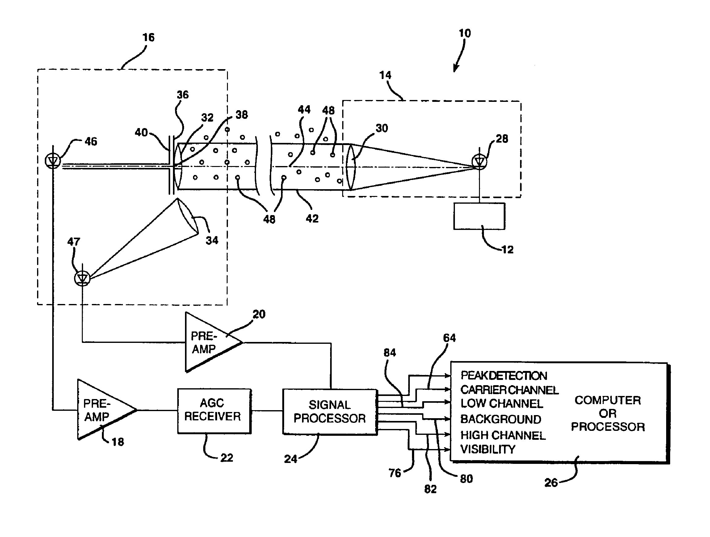
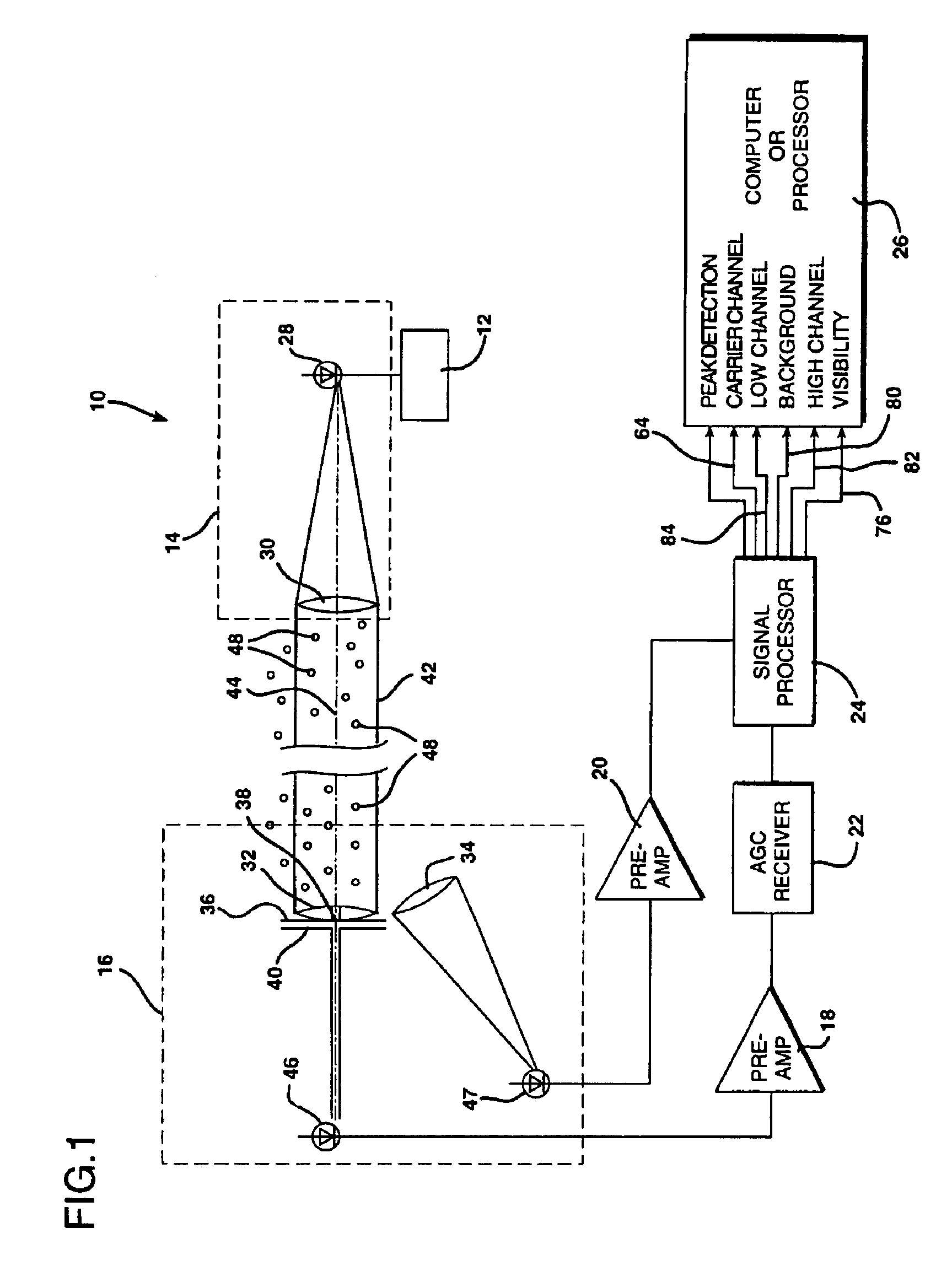
[0031]The present invention is based upon and operates much in the manner of the weather identification and visibility sensing system of U.S. Pat. No. 5,444,530, which is incorporated herein in its entirety by reference. FIG. 1 is a functional block diagram illustrating a weather identification system generally at 10 constructed according to the present invention. The weather identification system 10 includes an infrared (IRED) transmit modulator 12, a transmitter optical assembly 14, a receiver optical assembly 16, preamplification circuits 18 and 20, an AGC receiver 22, a signal processor 24, and a microprocessor unit 26 .

[0032]The transmitter optical assembly employs an infrared light emitting diode 28 and a one hundred millimeter transmitter culminating lens 30. The carrier signal generator 12 is coupled to produce a carrier signal at about forty six kilohertz to drive the light beam transmitting IRED photo transmitting diode 28.

[0033]The receiver optical assembly 16 includes a ...


PUM


Abstract

A weather identification system is provided which employs a first photosensitive receiver positioned directly in the path of a beam of light a predetermined distance from a partially coherent light beam source. The first photosensitive receiver is in direct optical communication with the light beam source to produce electronic signals in response to scintillations caused by particle movement between the source and the first receiver. A second photosensitive receiver is positioned out of the path of the beam of light and is oriented at an oblique angle relative thereto to provide an output indicative of forward scattering of light from scintillations that occur in the beam of light. The signals from the second photosensitive receiver are AC coupled to provide an output indicative of rate of fluctuation and having a signal strength characteristic that even distinguishes between light drizzle and fog. The weather identification system thereby senses precipitation, categorizes the precipitation as either rain or snow, and drizzle. The weather condition indicating system is ideal for use in remotely monitoring airfields.

Description

BACKGROUND OF THE INVENTION[0001]1. Field of the Invention[0002]The present invention relates to a system for optically and electronically ascertaining the existence and nature of precipitation and for measuring rain, snow, and drizzle in the ambient air from a remote location.[0003]2. Description of the Prior Art[0004]A light emitting diode weather identification system has previously been developed to remotely detect the existence of precipitation and to determine the nature of precipitation. That is, the prior weather identification system can differentiate between rain and snow. This prior weather identification system was established with the intent of automating surface weather observations at airports. The ability to completely automate surface observations is critically dependent on the ability to automatically distinguish between rain and snow. This prior system is disclosed in U.S. Pat. No. 4,760,272 issued on Jul. 26, 1988.[0005]The prior weather identification system is ...

Claims


Application Information

Patent Timeline
IPC IPC(8): G01N21/53G01N21/47G01W1/14
CPCG01N21/532G01N21/538G01W1/14G01N2021/4707
Inventor WANG, TING-I
Owner OPTICAL SCI
Why Eureka
Try Eureka