
Surface traffic movement system and method

a surface traffic and movement system technology, applied in the direction of navigation instruments, using reradiation, instruments, etc., can solve the problems of poor ground navigation, operational errors and deviations from procedures and directions, runway incursions, etc., to reduce the error of lost aircraft, curtail runway incursions, and increase the level of runway incursion safety

Inactive Publication Date: 2005-07-19
TECH PLANNING
View PDF13 Cites 46 Cited by
  • Summary
  • Abstract
  • Description
  • Claims
  • Application Information

AI Technical Summary

Benefits of technology

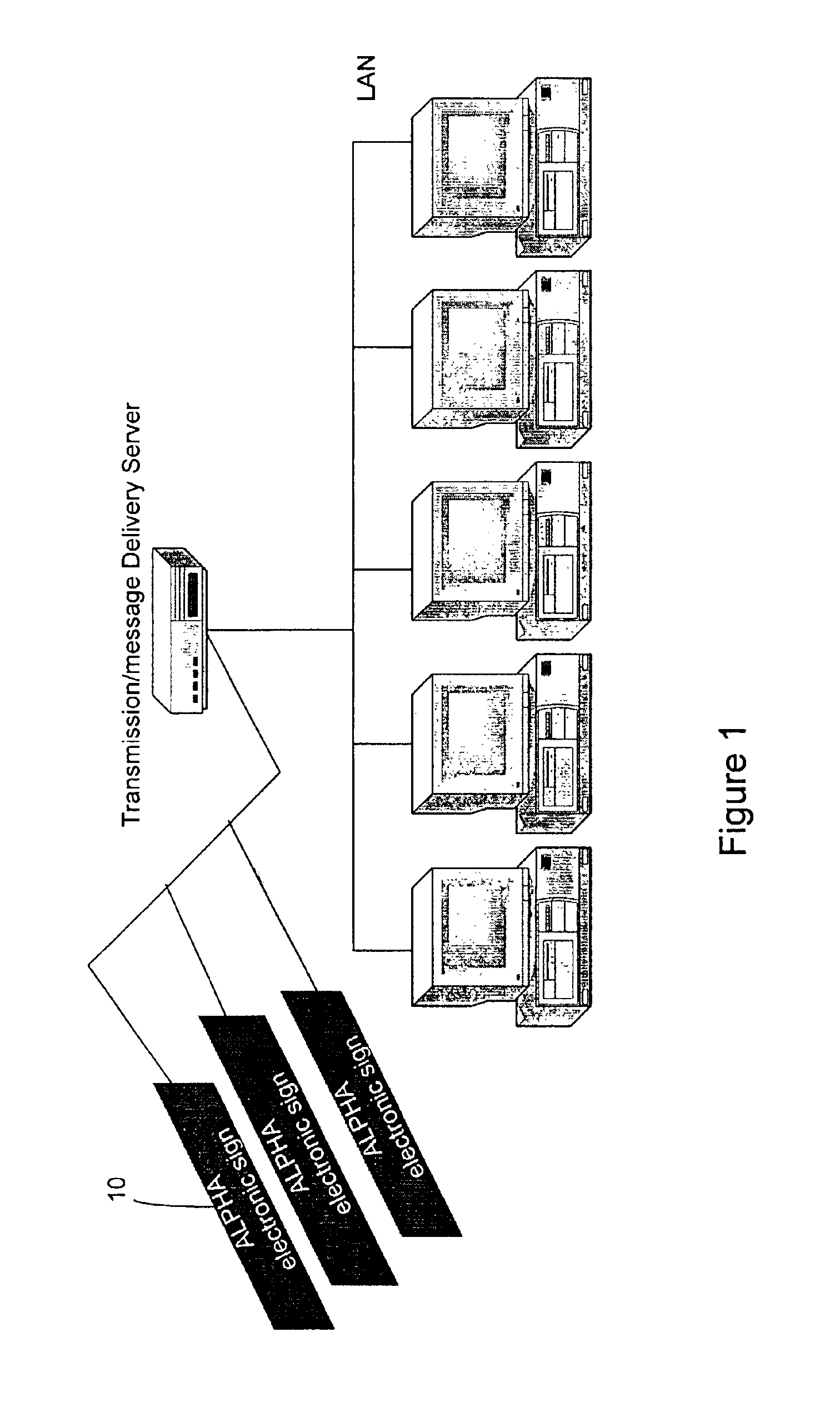
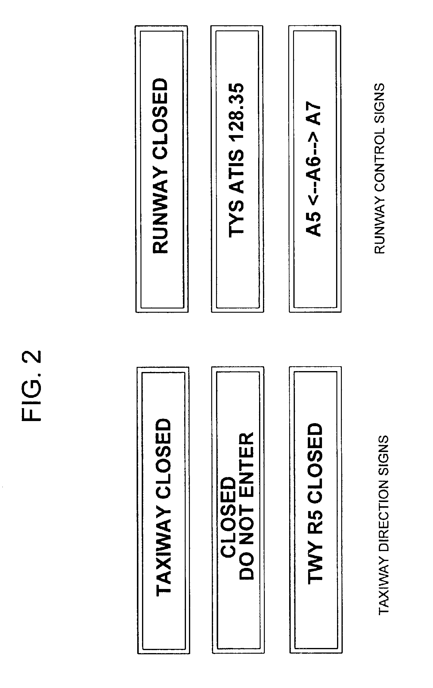
[0008]The present system virtually eliminates navigational and runway usage problems by providing visual guidance to aircraft and vehicles on the ground using detectors located on the runway / taxiway to detect the presence of an aircraft or vehicle and to provide specific guidance to the aircraft or vehicle via guidance display means such as electronic message boards or visual aids. The system displays unique taxi routes for each vehicle traveling on the runways / taxiways, and direct the aircraft pilot by the guidance display means at each traffic intersection as to whether his aircraft may enter and in which direction to proceed to attain his destination on the ground via such route. The system is designed to provide positive ground position information to ground traffic (aircraft and vehicles) instead of assumed location by visual sightings, to automatically keep track of all ground traffic operating on the runways / taxiways. The system permits an aircraft or vehicle operator, without any associated cooperative equipment, to report the message board key location identifier via any normal verbal communications equipment, thus locating the specific vehicle to a particular location on the airport surface area. For vehicles equipped with digital message signaling devices, the send / receive transceiver associated with the identified SMART Board is capable of receiving the vehicle signal and transmitting the data to an Air Traffic Control tower (central control facility). The message board key location identifier is an automatically generated name for a runway / taxiway position that changes on a periodic basis to preclude the pilot or vehicle operator from reporting an assumed location. That is, a unique location code can be generated daily by the system and visible on the message boards only at the specified locations to require a pilot to actually be at the location in order to read the key location identifier code. This capability is enabled by the airport-wide wireless transmission component of the system, or by a fixed wire equivalent. Via this capability and sensor generated positional data, the system automatically keeps track of all ground traffic operating on the runways / taxiways.
[0009]Thus, an object of the present invention is to address the causes of operational incidents in airport movement areas. The present invention provides for both Air Traffic Controllers and vehicles positive, unambiguous situational awareness, airport surface location, routing and air traffic control instructions. Thus, unsafe and incorrect vehicle movements are quickly recognized and less likely to occur. The “Silent Coordination” feature materially reduces voice frequency congestion because voice communication is used less to correct ambiguities or request repeated clearances. The System of the present invention has no airport-specific limitations and has additional advantages in supporting airport route changes necessitated by construction, weather and temporary conditions. The system can deliver critical aviation safety data to ground traffic at both towered and non-towered airports. Data may include advisories, Notices to Airmen (NOTAMS), Navigation Aids (NAVAIDs), status, restrictions and current airport conditions. The present invention's effectiveness is independent of aircraft type or crew proficiency and requires no vehicle equipage. The concepts are easily understood (as are the SMART Board messages) and require no extensive or sophisticated training. The System of the present invention is designed to be compatible with current Air Traffic Control (ATC) procedures. In a preferred embodiment, “controller” refers to the Air Traffic Controller.
[0010]The System of the present invention includes: complimentary current solutions designed to sense and react to incidents underway (effects) with solutions which address the precursor conditions (the causes) which lead to runway incursions such as—lack of situational awareness, misunderstanding of directions, aircraft location incorrect and / or executing unauthorized or unsafe aircraft movements. The present invention is fully compatible with current operational processes and constraints to assure acceptance and to effect minimal lead-time to operational deployment. There are no workload increases on Air Traffic Controller or pilots, and the “Silent Coordination” feature reduces Air Traffic Controller's workload and frequency congestion.

Problems solved by technology

Runway incursions are caused by human error, either by an Air Traffic Controller, a pilot, or a vehicle operator.
One or a combination of five primary factors cause operational errors and deviations from procedures and directions: position uncertainty and poor ground navigation; incorrect; incomplete or misinterpreted communications; improper clearances; lack of situational awareness; and human error.
Safety compromising incidents between aircraft are an insidious problem.
They are difficult to anticipate and difficult to analyze statistically, and they occur randomly with increasing frequency.
The reaction time required for a pilot or air traffic tower controller to detect, evaluate, and resolve a conflict is extremely short.
Prior solutions such as sensors that provide collision avoidance advisories subject to limited reaction times (measured in seconds) to correct a safety incident already in progress are inadequate because separation standards have already been violated.
Runway Land and Hold Short Lighting Systems are helpful for go-no-go situations but are not capable of presenting necessary safety-related situational information or directional information.
Prior art solutions do not take into account the complexities and interdependencies of surface movement operations.

Method used


Image

  • Surface traffic movement system and method
  • Surface traffic movement system and method
  • Surface traffic movement system and method

Examples


Embodiment Construction

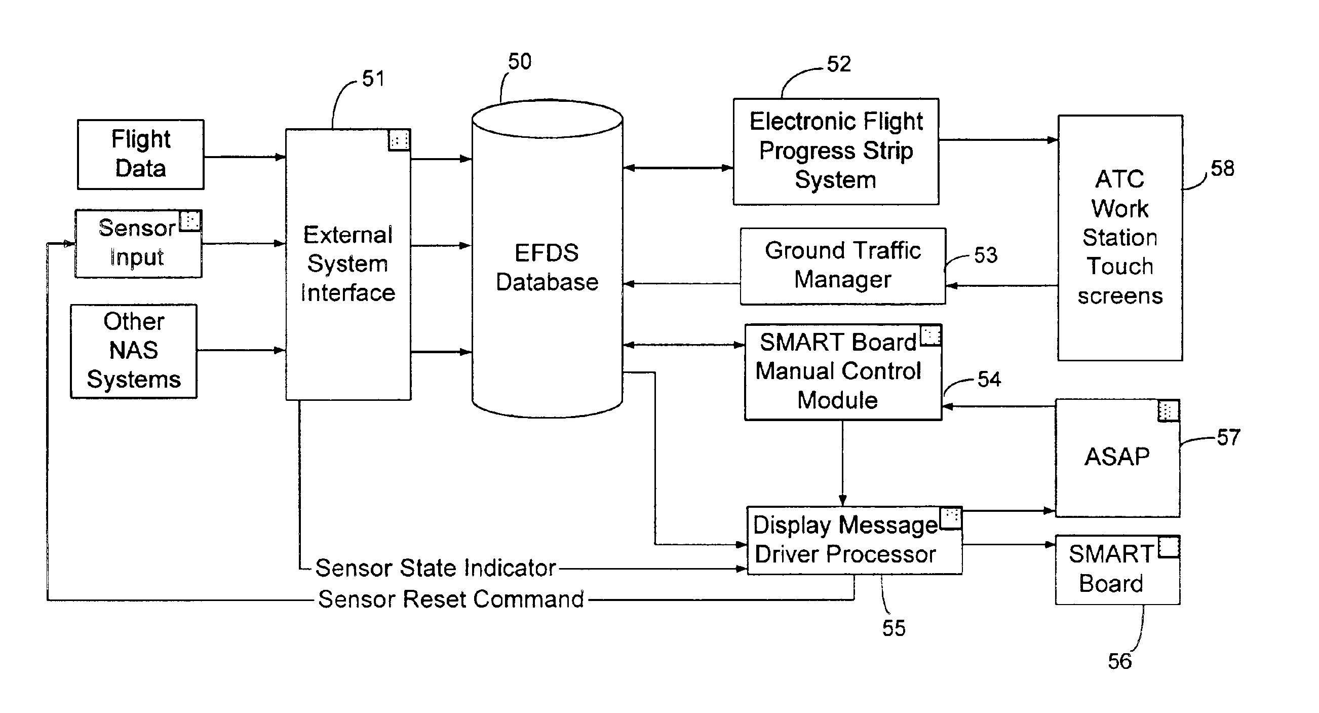
[0033]The System of the present invention includes five main components: 1) sensors, 2) surface movement area / runway traffic (SMART) Board Surface Displays, 3) wireless LAN communicators, and 4) Electronic Flight Data System (EFDS) processor for electronic flight management, and 5) Surface Area Flow Tool with Runway Incursion Protection (SAFTRIP). In the preferred embodiment, the system of the present invention includes: programmable message boards installed next to taxiways, ramps and runway intersections; radar sensors or magnetic inductive loop sensors installed in taxiways to detect vehicle and movement direction; and wireless LAN transceivers that provide connectivity between loop sensors, sign boards, and EFDS interface. The system is designed to accept a wide variety of sensor inputs in addition to loop and radar sensors.

[0034]Turning now to the sensor component, Display Message Driver Processor (DMDP) module of the EFDS generates SMART Board Surface Display messages based on...


PUM


Abstract

A Surface Movement Area / Runway Traffic and Surface Area Flow Tool with Runway Incursion Protection System reduces runway incursions due to lost or disoriented aircraft, navigation in low visibility conditions, unfamiliarity with local procedures and airport layouts, and truncated or misunderstood clearances or other frequency congestion related communication and workload problems. SMART Board surface displays are used to provide route guidance instructions to aircraft at ramp and taxiway intersections, confirm to for pilots that their aircraft is at the correct location and is in the assigned queue and sequence before entering active runways, visual confirmation of runway clearances to aircraft and vehicles at all runway entrances, and lessening frequency congestion on Ground and Local communications channels. The system includes an Electronic Flight Data System to generate messages. Sensors and a wireless LAN are used to provide data from the system to all aircraft and vehicles on the surface movement area of an airport.

Description

[0001]This application claims benefit of U.S. Provisional Patent Application No. 60 / 291,644 filed on May 18, 2001.FIELD OF THE INVENTION[0002]This invention relates to surface traffic management systems, and more particularly to the visual depiction of selected route guidance of individual vehicles, such as identified aircraft.BACKGROUND OF THE INVENTION[0003]Runway Incursions occur when aircraft or vehicles enter onto a runway and conflict with aircraft cleared to land or take off on the same runway. Runway incursions are caused by human error, either by an Air Traffic Controller, a pilot, or a vehicle operator. One or a combination of five primary factors cause operational errors and deviations from procedures and directions: position uncertainty and poor ground navigation; incorrect; incomplete or misinterpreted communications; improper clearances; lack of situational awareness; and human error.[0004]Safety compromising incidents between aircraft are an insidious problem. They ar...

Claims


Application Information

Patent Timeline
Patent Type & Authority Patents(United States)
IPC IPC(8): G08G5/06G08G5/00
CPCG08G5/0026G08G5/065
Inventor MALLET, ROBERTCALZETTA, ROBERT
Owner TECH PLANNING
Learn More