Vaporizer delivery ampoule

a technology of vaporizer and ampoule, which is applied in the field of vaporizer, can solve the problems of failure to reliably and reproducibly deliver solid precursors to the reaction chamber, the type and composition of the layers that can be formed using cvd is limited, and the procedure is unsuccessful

Inactive Publication Date: 2005-07-26
ENTEGRIS INC
View PDF17 Cites 212 Cited by
  • Summary
  • Abstract
  • Description
  • Claims
  • Application Information

AI Technical Summary

Benefits of technology

[0078]FIG. 8 illustrates the distribution of heat from the ampoule to a protuberance positioned in container 5. The temperature is raised to 130° C. and heat distribution within the ampoule was nearly constant after the first hour of vaporization. Because the multiple containers provide an increased area for placement of the precursor material more product may be produced without refilling of the ampoule thereby reducing off-time of the instrument.

Problems solved by technology

The type and composition of the layers that can be formed using CVD is limited by the ability to deliver the reactants or reactant precursors to the surface of the substrate.
Analogous attempts have been made to deliver solid reactants to a CVD reaction chamber, but with much less success.
However, this procedure has been unsuccessful in reliably and reproducibly delivering solid precursor to the reaction chamber for a number of reasons.
The major problems with the technique are centered on the inability to consistently vaporize a solid at a controlled rate such that a reproducible flow of vaporized solid precursor can be delivered to the process chamber.
Also, it is difficult to ensure complete saturation of the fast flowing carrier gas stream because of a limited amount of exposed surface area of the solid precursor in the vaporizer system and lack of uniform temperature to provide maximum sublimation.
Similar problems are inherent in conventional ion implantation systems that include an ion source in which a dopant element is ionized and then subsequently accelerated to form an ion beam directed at a workpiece surface for implantation.
Solid ion source material is greatly preferred for safety reasons, however, solid semiconductor dopants have presented serious technical and operating problems.
For instance, utilization of a solid precursor material in vaporizers causes extended down time of the instrumentation, poor product quality, and deposit buildup within the vaporizer.
Prior art vaporizer systems have numerous disadvantages, including buildup of condensed material within the vaporizers, and formation of “cold spots” within the interior of the vaporizers due to lack of uniform heating therein.
Additionally, due to the buildup of deposits on internal moving mechanisms, operation of these vaporizers is not efficient or reliable.
Thus, it is difficult to vaporize a solid at a controlled rate such that a reproducible flow of vaporized solid precursor can be delivered to a downstream deposition system.

Method used


Image

  • Vaporizer delivery ampoule
  • Vaporizer delivery ampoule
  • Vaporizer delivery ampoule

Examples


example i

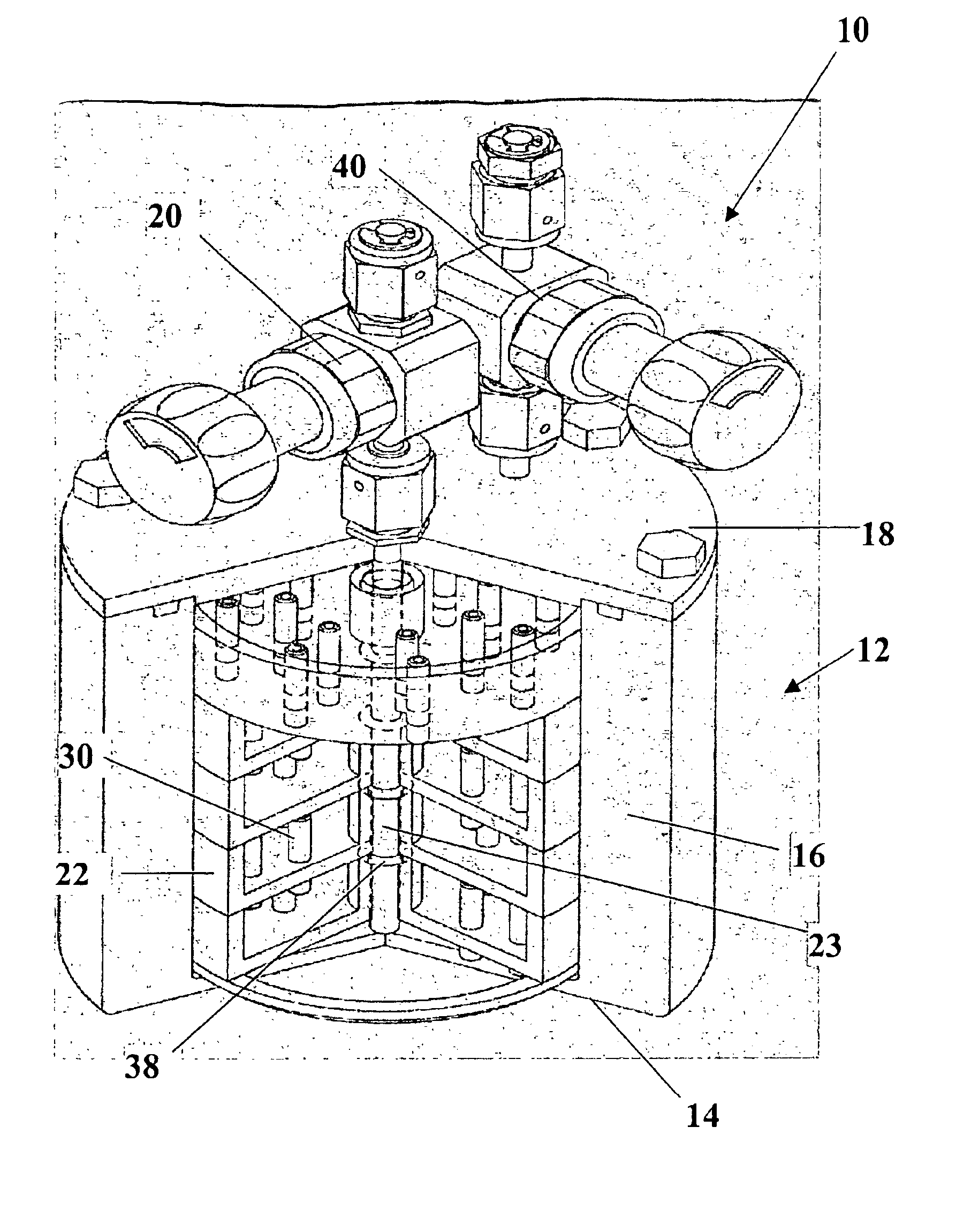
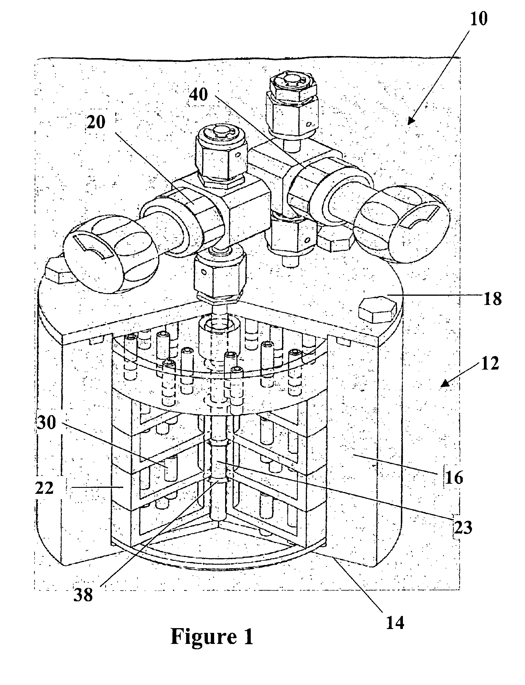
[0077]The vaporizer of the present invention comprising a container unit having 5 stacked containers within an ampoule of the present invention such as shown in FIG. 1 was tested to determine the effectiveness of heat conductance from the ampoule to the containers. The ampoule was made of high grade stainless steel and connected to a block heater having a shape fitting around the circumference of the ampoule. The heater was connected to a variable transformer which is a source of variable AC voltage and controls the degree of heating. Several of the individual containers, container 1 and 5, positioned within the ampoule were connected to temperature sensors to determine the evenness of heating and effectiveness of heat transference from the ampoule to the containers. The ampoule was connected to a source of carrier gas for introduction into the ampoule and through the container unit at about 500 sccm. As shown in FIG. 7, as the temperature is increased in the heater attached to the ...


PUM

PropertyMeasurementUnit
temperaturesaaaaaaaaaa
pore sizeaaaaaaaaaa
inner diameteraaaaaaaaaa

Abstract

A vaporizer delivery system for use in semiconductor manufacturing processes including a plurality of vertically stacked containers for holding a vaporizable source material. Each of the vertically stacked containers includes a plurality of vented protuberances extending into the interior of the each stacked container thereby providing channels for passage of a carrier gas between adjacent vertically stacked containers.

Description

BACKGROUND OF INVENTION[0001]1. Field of the Invention[0002]The present invention relates to a vaporizer, and more particularly, to a vaporizer delivery system having multiple containers to provide increased surface area for vaporization of liquids and solid materials, e.g., liquid and solid source reagents used in chemical vapor deposition (CVD), atomic layer chemical vapor deposition (ALCVD) and ion implantation processes.[0003]2. Description of the Related Art[0004]Chemical vapor deposition (CVD) has been extensively used for preparation of films and coatings in semiconductor wafer processing. CVD is a favored deposition process in many respects, for example, because of its ability to provide highly conformal and high quality films, at relatively fast processing times. Further, CVD is beneficial in coating substrates of irregular shapes including the provision of highly conformal films even with respect to deep contacts and other openings.[0005]In general, CVD techniques involve ...

Claims


Application Information

Patent Timeline
Patent Type & Authority Patents(United States)
IPC IPC(8): C23C16/448
CPCC23C16/4481F17C3/00Y02E60/321Y10S261/65C23C16/4483Y02E60/32F17C3/02F17C11/00F17C2203/03C23C16/4408C23C16/45544C23C16/50
Inventor GREGG, JOHNBATTLE, SCOTTBANTON, JEFFREY I.NAITO, DONNFUIERER, MARIANNE
Owner ENTEGRIS INC
Why Eureka
Try Eureka