Substrate structure for growth of highly oriented and/or epitaxial layers thereon

a substrate structure and highly oriented technology, applied in the field of composite substrate structure, can solve the problems of silicon nitride layer migration and other materials in the system, and the deposition of the ysz layer was considered too slow for commercial production,

Inactive Publication Date: 2005-07-26
TRIAD NAT SECURITY LLC
View PDF22 Cites 69 Cited by
  • Summary
  • Abstract
  • Description
  • Claims
  • Application Information

AI Technical Summary

Benefits of technology

[0016]The present invention also provides a superconducting article including a flexible polycrystalline metal substrate, a layer of a crystalline metal oxide or crystalline metal oxynitride material upon the flexible polycrystalline metal substrate, a layer of an oriented cubic oxide material having a rock-salt-like structure upon the crystalline metal oxide or crystalline metal oxynitride material layer, at least one layer of a buffer material upon the oriented cubic oxide material layer, and a top-layer of a high temperature superconducting material

Problems solved by technology

While the performance was satisfactory, the deposition of the YSZ layer was considered too slow for commercial production.
A potential drawback in the use of such amorphous silicon nitride sur

Method used


Image

  • Substrate structure for growth of highly oriented and/or epitaxial layers thereon
  • Substrate structure for growth of highly oriented and/or epitaxial layers thereon
  • Substrate structure for growth of highly oriented and/or epitaxial layers thereon

Examples


example 1

[0048]A nickel alloy substrate (Hastelloy C276) was ultrasonically cleaned in soap and water, rinsed with deionized water, rinsed with methanol and blown dry with filtered nitrogen. A layer of aluminum oxide about 350 angstroms in thickness was deposited by ion beam sputter deposition. Onto this resultant article was deposited a layer of crystalline yttrium oxide (about 70 angstroms in thickness) also by ion beam sputter deposition.

[0049]An ion-assisted, electron beam evaporation system similar to that of Wang et al., App. Phys. Lett., v. 71, no. 20, pp. 2955-2957 (1997), was used to deposit a MgO film upon a flexible metal substrate of Hastelloy C-276 or other nickel-based alloys. The ion source was manufactured by Ion Tech, Inc. (Ft. Collins, Colo.) with a source geometry of 22 cm by 2.5 cm. The substrate normal to ion-assist beam angle was 45±3°. The ion source gas was argon. The ion source gas was introduced to a background partial pressure of about 1.0×10⁻⁶ Torr with a total pr...

example 2

[0052]Another run similar to example 2 was conducted with the differences that a layer of crystalline erbium oxide (about 100 angstroms in thickness) deposited by e-beam evaporation was used in place of the yttrium oxide and the YBCO layer was about 1.6 microns in thickness. The Jc was measured as 1.1×10⁶ A / cm2 using a standard four-point measurement. The projected Ic is 175 Amperes across a sample 1 cm wide.

example 3

[0053]Another run similar to example 3 was conducted with the differences that no aluminum oxide layer was used between the metal substrate and the erbium oxide layer and the YBCO layer was about 1.3 microns in thickness. The Jc was measured as 0.28×10⁶ A / cm2 using a standard four-point measurement.

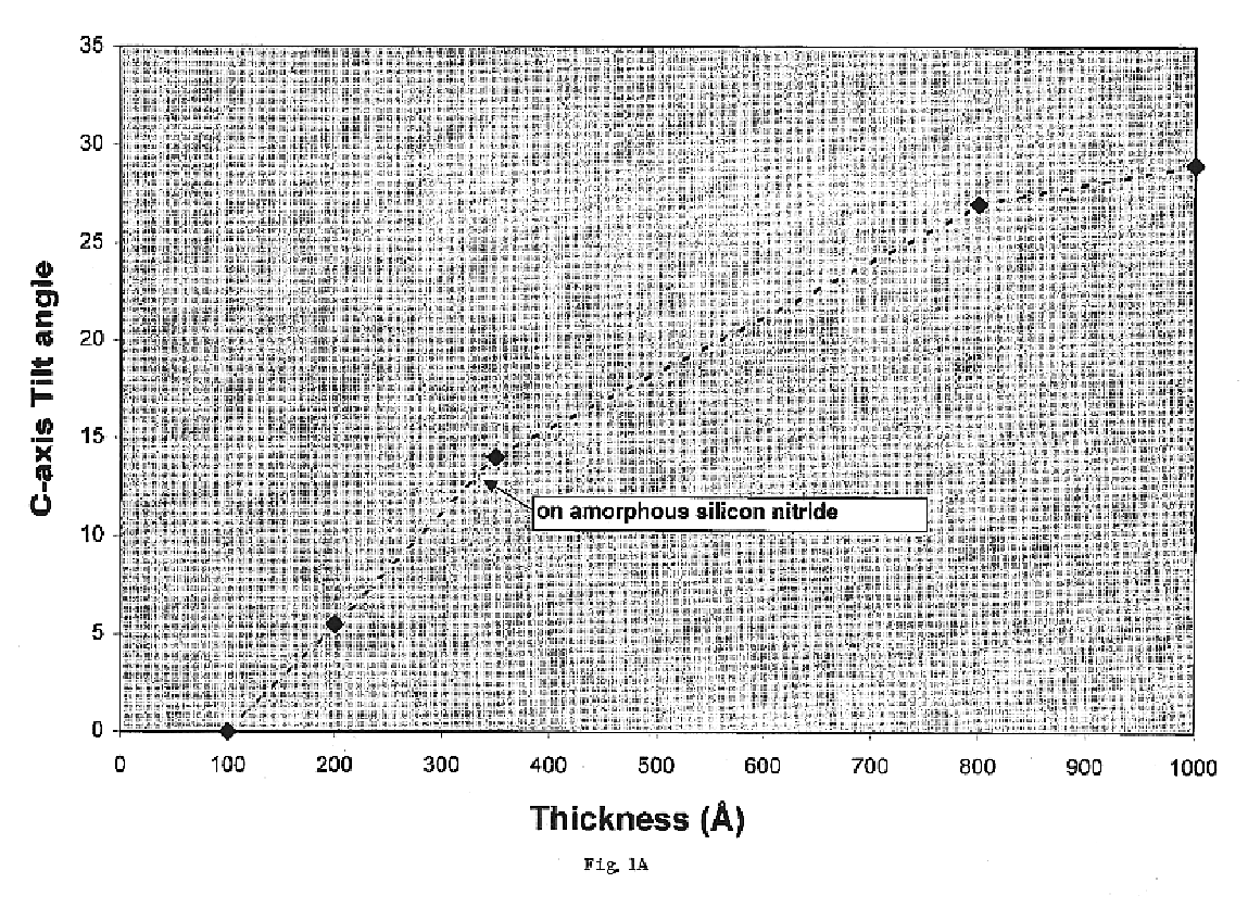
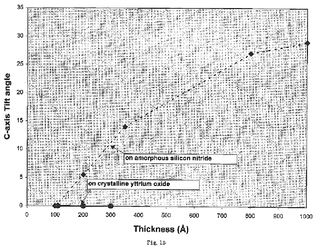
[0054]The results of the present examples demonstrate that the successful use of crystalline metal oxide materials as the layer onto which an oriented layer of MgO or another oriented cubic oxide material having a rock-salt-like structure is deposited.


PUM

PropertyMeasurementUnit
Lengthaaaaaaaaaa
Currentaaaaaaaaaa
Nanoscale particle sizeaaaaaaaaaa

Abstract

A composite substrate structure including a substrate, a layer of a crystalline metal oxide or crystalline metal oxynitride material upon the substrate, a layer of an oriented cubic oxide material having a rock-salt-like structure upon the crystalline metal oxide or crystalline metal oxynitride material layer is provided together with additional layers such as one or more layers of a buffer material upon the oriented cubic oxide material layer.
Jc′s of 2.3×10⁶ A/cm2 have been demonstrated with projected Ic′s of 320 Amperes across a sample 1 cm wide for a superconducting article including a flexible polycrystalline metallic substrate, an inert oxide material layer upon the surface of the flexible polycrystalline metallic substrate, a layer of a crystalline metal oxide or crystalline metal oxynitride material upon the layer of the inert oxide material, a layer of an oriented cubic oxide material having a rock-salt-like structure upon the crystalline metal oxide or crystalline metal oxynitride material layer, a layer of a buffer material upon the oriented cubic oxide material layer, and, a top-layer of a high temperature superconducting material upon the layer of a buffer material.

Description

[0001]This application is a continuation-in-part of Ser. No. 09 / 731,534, filed Dec. 6, 2000 now abandoned, by Arendt et al.STATEMENT REGARDING FEDERAL RIGHTS[0002]This invention was made with government support under Contract No. W-7405-ENG-36 awarded by the U.S. Department of Energy. The government has certain rights in the invention.FIELD OF THE INVENTION[0003]The present invention relates to a composite substrate structure for subsequent growth of highly oriented and / or epitaxial layers thereon. For example, high temperature superconducting thick films can be grown epitaxially on such composite substrate structures with high Jc′s and Ic′s.BACKGROUND OF THE INVENTION[0004]The preparation of oriented layers of crystallographically materials is critical in a number of technical areas. For example, high temperature superconductors often employ epitaxially oriented layers of, e.g., YBCO to achieve desired properties. Similarly, epitaxially oriented films such as conductive oxides, fer...

Claims


Application Information

Patent Timeline
IPC IPC(8): C23C14/08C30B23/02H01L39/24
CPCC23C14/081C30B23/02H01L39/2461C30B29/225C30B29/22Y10T428/265H10N60/0632
Inventor ARENDT, PAUL N.FOLTYN, STEPHEN R.GROVES, JAMES R.JIA, QUANXI
Owner TRIAD NAT SECURITY LLC
Why Eureka
Try Eureka