Method for implementing an efficient and economical cathode process

a cathode and process technology, applied in the manufacture of electrode systems, instruments, electric discharge tubes/lamps, etc., can solve the problems of reducing the efficiency and productivity of manufacturing lines, and consuming only a small fraction of the power used by traditional cathode hot cathodes. , to achieve the effect of reducing manufacturing costs, reducing manufacturing costs, and reducing manufacturing costs

Inactive Publication Date: 2005-08-02
SONY CORP +2
View PDF9 Cites 0 Cited by
  • Summary
  • Abstract
  • Description
  • Claims
  • Application Information

AI Technical Summary

Benefits of technology

[0017]The present invention provides, in one embodiment, a method of fabricating a cathode requiring relatively few and somewhat simple steps. In one embodiment, the present invention also provides a method of fabricating a cathode which eliminates a passivation layer patterning steps, a direct via patterning step, and a metallic gate patterning step. Further, in one embodiment, the present invention also provides a method of fabricating a cathode which reduces manufacturing costs and increases the efficiency and productivity of manufacturing lines engaged in cathode fabrication. Further still, the present invention provides, in one embodiment, a method of fabricating a cathode which reduces the unit cost of thin CRTs manufactured therewith.
[0018]In one embodiment, a novel method effectuates fabrication of a cathode by a process requiring relatively few and somewhat simpler steps. The process, in one embodiment, involves a number of steps involving technologies well known in the art. Importantly however, in one embodiment, the requirement for at least one of the passivation layer patterning steps, required by conventional cathode fabrication processes, is eliminated. In one embodiment, a direct via patterning step, required by conventional cathode fabrication processes, is eliminated. In one embodiment, a metallic gate chromium (or other metal) patterning step, required by conventional cathode fabrication processes, is eliminated. One embodiment eliminates a passivation layer patterning step, a direct via patterning step, and a metallic gate patterning step.
[0019]The elimination of a direct via masking step in accordance with one embodiment of the present effectively eliminates or substantially reduces costs conventionally associated with executing the step and concomitantly reduces the total time necessary to complete the entire process. Advantageously, this increases production line efficiency and productivity, correspondingly reducing fabrication costs and unit costs of finished devices manufactured therewith.

Problems solved by technology

These emitters EE use cold cathode technology, which consumes only a small fraction of the power used by the traditional CRT's hot cathode.
However, cathodes for thin CRTs have relatively complex designs, as well as certain unique structural features and material compositions, which tend to complicate their manufacture, in accordance with conventional methods.
One conventional process of fabricating 1 micron scale Spindt emitters 55 requires several relatively slow and costly photolithographic steps.
Additionally, at 1 micron gate widths, more expensive integrated circuit drivers rated at 80 volts are needed.
This voltage range results in a high power consumption that is unacceptable for portable applications.
From a manufacturing cost standpoint this is significant because the one very small element, the cathode emitter, has large redundancy.
The level of cathodic structural complexity and the nature of constituent materials involved, including lanthanides and group VI B metals and others, has resulted in elaborate fabricative procedures, often with repetitive and reiterative operations.
Such repetitive or reiterative operations render the conventional art problematic for four related reasons.
This is elaborate, inefficient, and costly.
It is especially wasteful in fabricating the M1 and M2 pad areas.
Further, no conventional technique exists for combining various repetitive and / or analogous steps or stages of cathode fabrication processes.
The first problem arising from the conventional art is that the elaborate conventional methods are expensive, individually and cumulatively.
Second, the complexity of the conventional art, especially with respect to the relatively large number of steps it requires, consumes inordinate time.
Third, this renders the production lines involved correspondingly less efficient and productive than desirable, with correspondingly increased costs.
And fourth, the total unit cost of the cathode assembly, and correspondingly, complete thin CRT units, is higher than desirable.

Method used


Image

  • Method for implementing an efficient and economical cathode process
  • Method for implementing an efficient and economical cathode process
  • Method for implementing an efficient and economical cathode process

Examples


Embodiment Construction

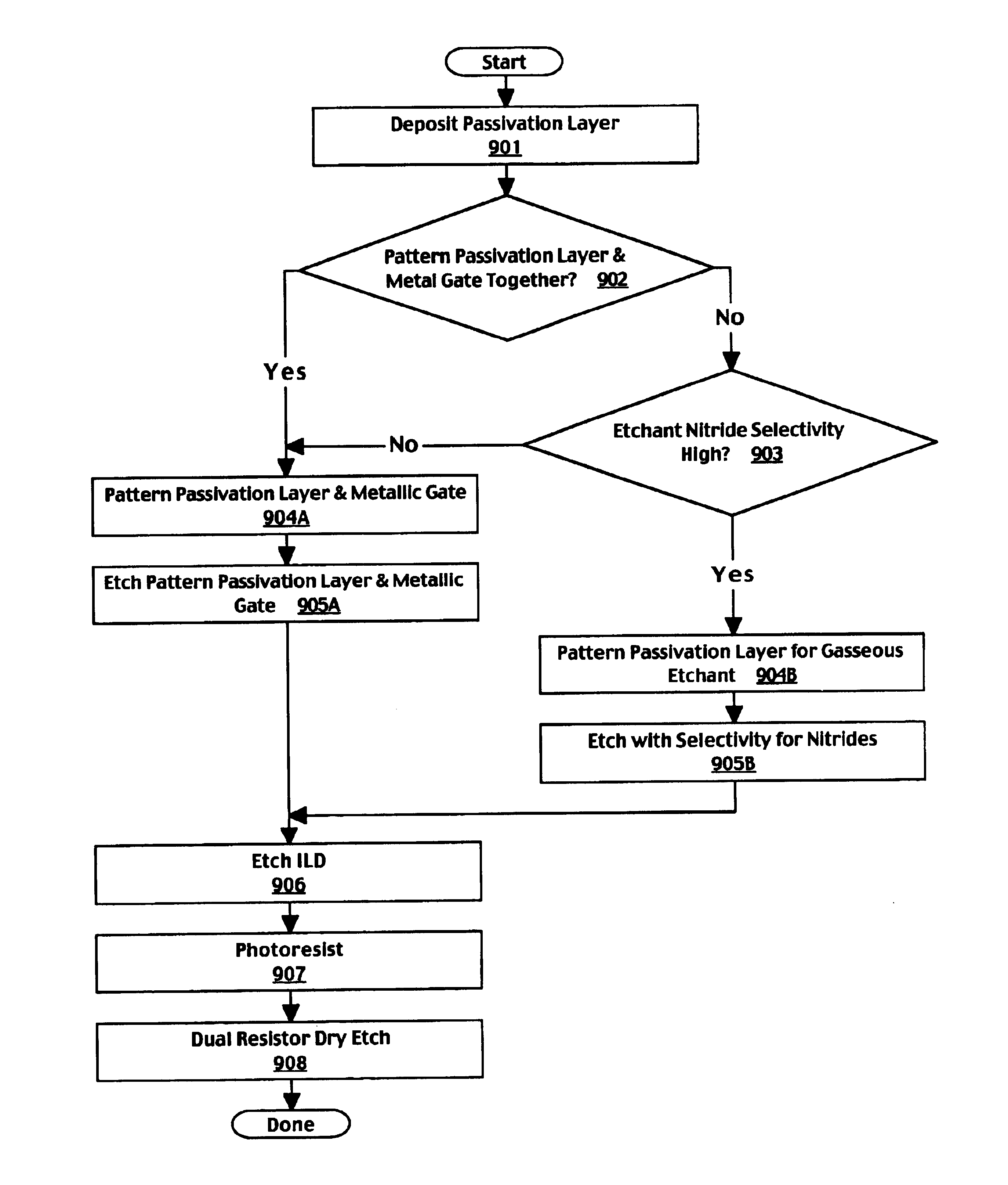
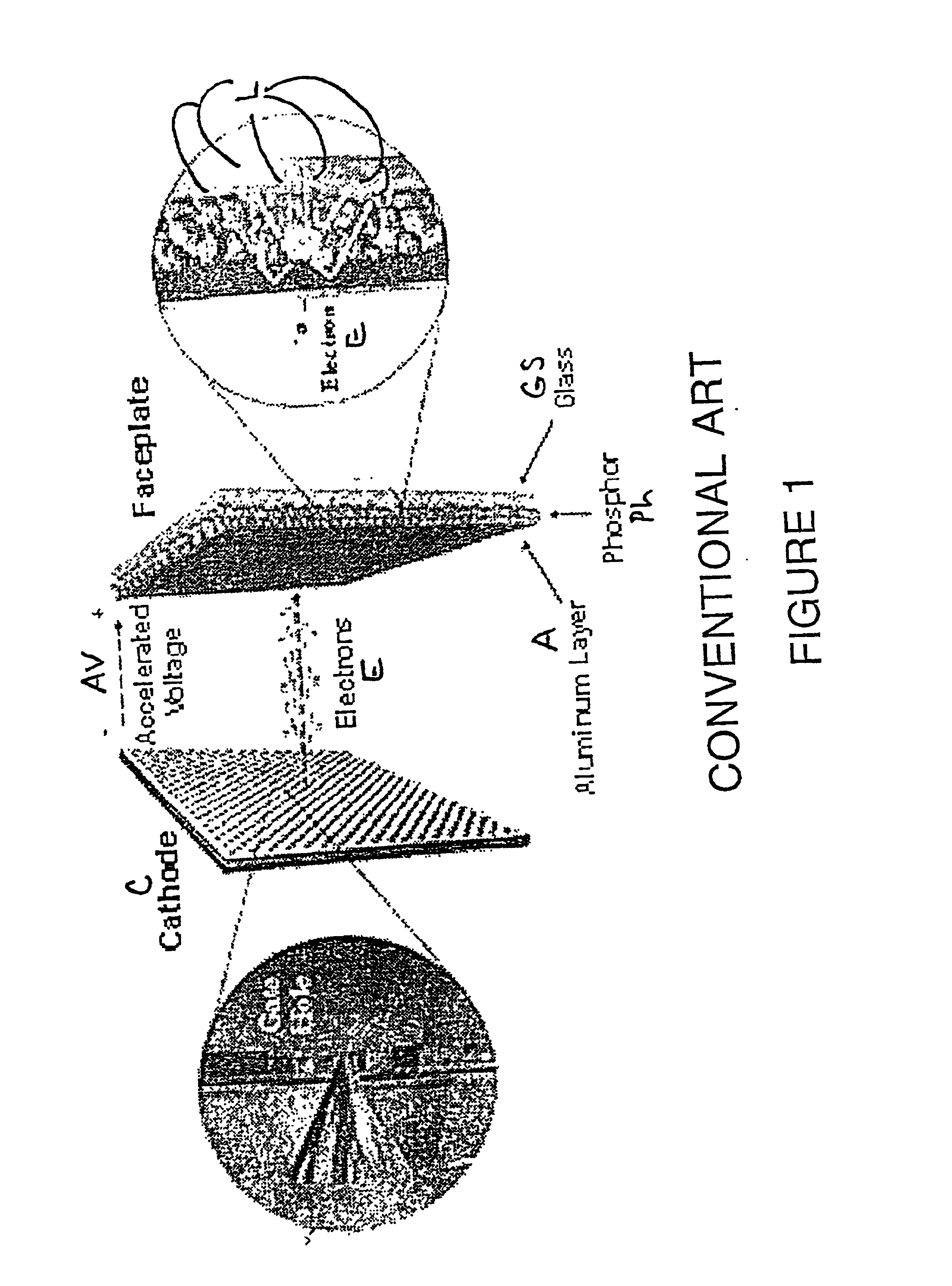
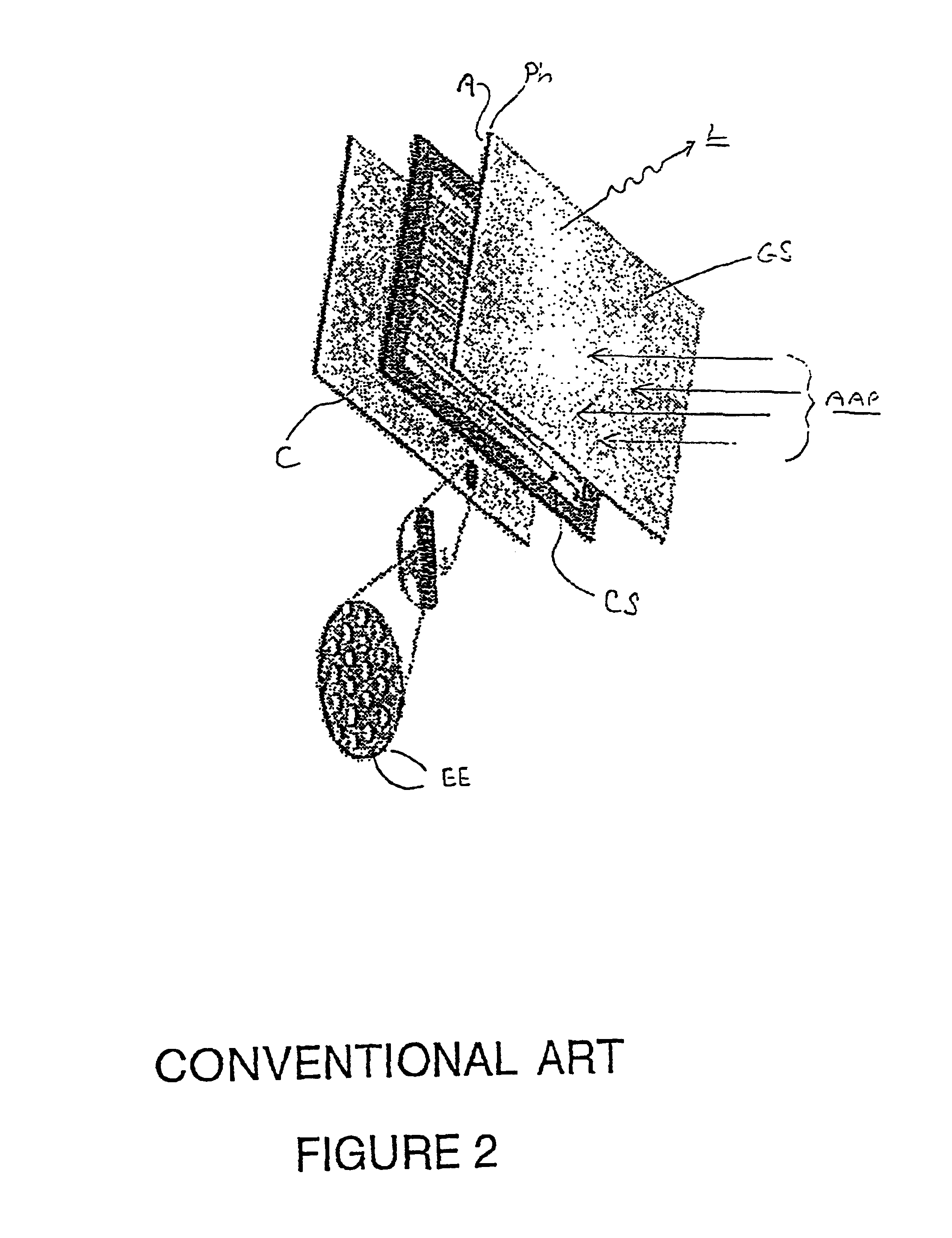
[0054]Reference will now be made in detail to the preferred embodiments of the invention, examples of which are illustrated in the accompanying drawings. While the invention will be described in conjunction with the preferred embodiments, it will be understood that they are not intended to limit the invention to these embodiments. On the contrary, the invention is intended to cover alternatives, modifications and equivalents, which may be included within the spirit and scope of the invention as defined by the appended claims.

[0055]Furthermore, in the following detailed description of the present invention, numerous specific details are set forth in order to provide a thorough understanding of the present invention. However, it will be obvious to one of ordinary skill in the art that the present invention may be practiced without these specific details. In other instances, well-known methods, procedures, components, and compounds have not been described in detail so as not to unneces...


PUM

PropertyMeasurementUnit
gate widthsaaaaaaaaaa
areaaaaaaaaaaa
thicknessaaaaaaaaaa

Abstract

The present invention provides a method of fabricating a cathode requiring relatively few and somewhat simple steps. In one embodiment, a novel etchant gas chemistry dispenses with needing a second passivation layer. In one embodiment, a direct via is formed without a separate mask. In one embodiment, access and isolation features of a metallic gate are patterned in the same patterning operation as an associated passivation layer, dispensing with a need for separate patterning of each. In one embodiment, etching is effectuated with high selectivity for nitrides of silicon. In one embodiment, the requirement for at least one passivation layer deposition, a direct via masking step, and separate patterning steps for the passivation layer and metallic gate are eliminated. This effectively eliminates or substantially reduces associated costs, concomitantly reducing process completion time. Advantageously, this increases efficiency and productivity, correspondingly reducing fabrication costs and unit costs of finished devices.

Description

TECHNICAL FIELD[0001]The present invention relates to processes for manufacturing cathode ray tubes. In particular, the present invention pertains to a novel method for implementing an efficient and economical process for fabricating a cathode for use in a cathode ray tube.BACKGROUND ART[0002]The flat panel or thin cathode ray tube (CRT) is a widely and increasingly used display device. Thin CRTs, such as the ThinCRT™ of Candescent Technologies Corp., San Jose, Calif., are used in desktop and workstation computer monitors, panel displays for many control and indication, test, and other systems, and television screens, among a growing host of other modern applications.[0003]Thin CRTs work on the same basic principles as standard CRTs. Referring to Conventional Art FIG. 1, beams of electrons E are fired from negatively-charged electrodes, e.g., cathodes C, through an accelerating potential AV in an evacuated glass tube T. The electrons E strike phosphors Ph in front of an aluminum (Al...

Claims


Application Information

Patent Timeline
Patent Type & Authority Patents(United States)
IPC IPC(8): H01J9/02H01J1/30
CPCH01J1/30H01J9/148
Inventor LEE, JUENG-GILBONN, MATTHEW A.KEMMOTSU, HIDENORIKIKUCHI, KAZUO
Owner SONY CORP
Why Eureka
Try Eureka