Optical apparatus

a technology of optical equipment and filters, applied in the field of optical equipment, can solve the problems of affecting the optical performance of the image, affecting the image quality, and affecting the image taken due to the increase of focal depth, so as to reduce the thickness of the filter, the effect of reducing the influence of the filter to be inserted into the image taking optical system and reducing the deterioration of optical performan

Inactive Publication Date: 2005-08-02
CANON KK
View PDF10 Cites 22 Cited by
  • Summary
  • Abstract
  • Description
  • Claims
  • Application Information

AI Technical Summary

Benefits of technology

[0032]Furthermore, it is allowed that the above filer member is formed by a multilayer film. To generate a density change by a filter, it is possible to form a filter member by using a multilayer film and controlling a density change freely to a certain extent and decrease the thickness of a filter (base transparent plate) required to generate a density. Thereby, the above mentioned is preferable because influences of the filter to be inserted into a image taking optical system decrease, deterioration of optical performances decrease, and the correction amount of a focus lens decreases. Furthermore, it is preferable to constitute the above multilayer film so as to have a layer for deteriorating reflection. When a flat plate such as a filter is present in an image taking optical system, it causes a ghost or flare. Therefore, by forming the above filter into a multilayer film and thereby forming an antireflection film, it is possible to reduce ghosts and flares.
[0033]Furthermore, correction of a focus position caused by the above filter member is performed when the above corrected aperture stop value is present in a range between F No. 2.0 of the image taking optical system and an aperture stop closed state. The filter is inserted into the image taking optical system at an aperture stop value when an aperture stop is slightly closed from its opened state. However, to prevent the focusing performance from being deteriorated due to a diffraction phenomenon caused when the opening diameter of the aperture stop decreases, it is important to cover by the filter in a state of a slightly bright F No. Therefore, because the filter completely covers between F No. 2.0 and F No. 11.0 and thereafter, the completely covered state continues until the aperture stop closes. Therefore, by using a focus displacement caused during the above period as a correction amount of a focus lens, it is possible to construct a proper optical apparatus.

Problems solved by technology

When image taking an object with a still camera or video camera, if an aperture stop diameter becomes too small though the object is bright, deterioration of image quality due to diffraction and dust image taken due to increase of focal depth become issues.
Moreover, when removing an infrared cut filter normally used for image taking from an optical path, a focus position is displaced.
In the case of Japanese Patent Application Laid-Open No. 11-289487, though a focus lens correction amount corresponding to an insertion amount of an ND filter is used, there is a problem that an accurate correction amount cannot be obtained by only the insertion amount of the ND filter because the rate of the area covered with the ND filter in the opening area of an optical path depends on an opening diameter of an aperture stop.
Moreover, in the case of Japanese Patent Application Laid-Open Nos. 11-72691and 11-305107, there is a problem that an accurate correction amount cannot be obtained because a state is assumed in which an optical component such as an ND filter completely covers or completely removes from an optical path but image taking when the ND filter half covers the optical path is not considered.

Method used


Image

  • Optical apparatus
  • Optical apparatus
  • Optical apparatus

Examples


first embodiment

(First Embodiment)

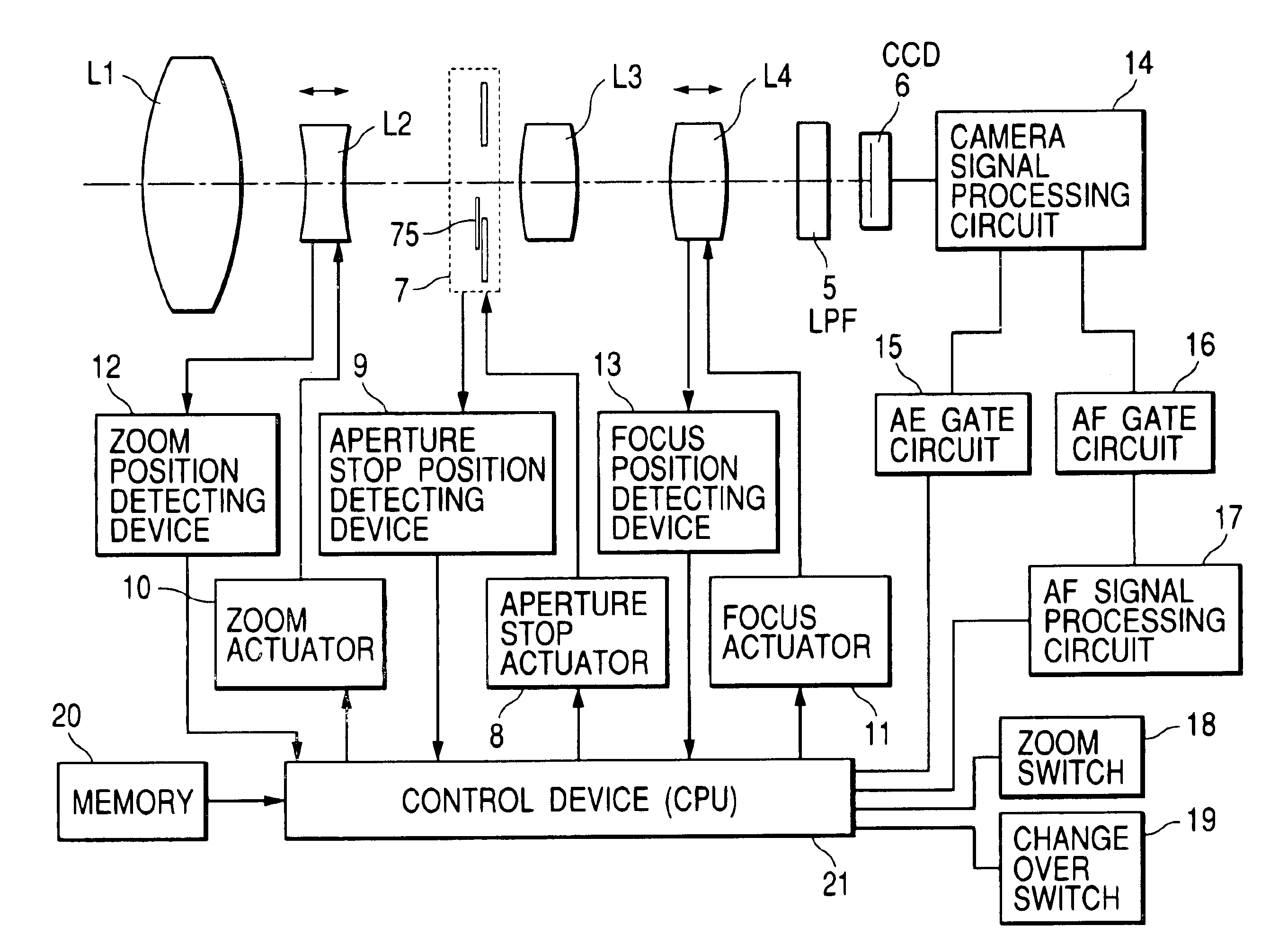
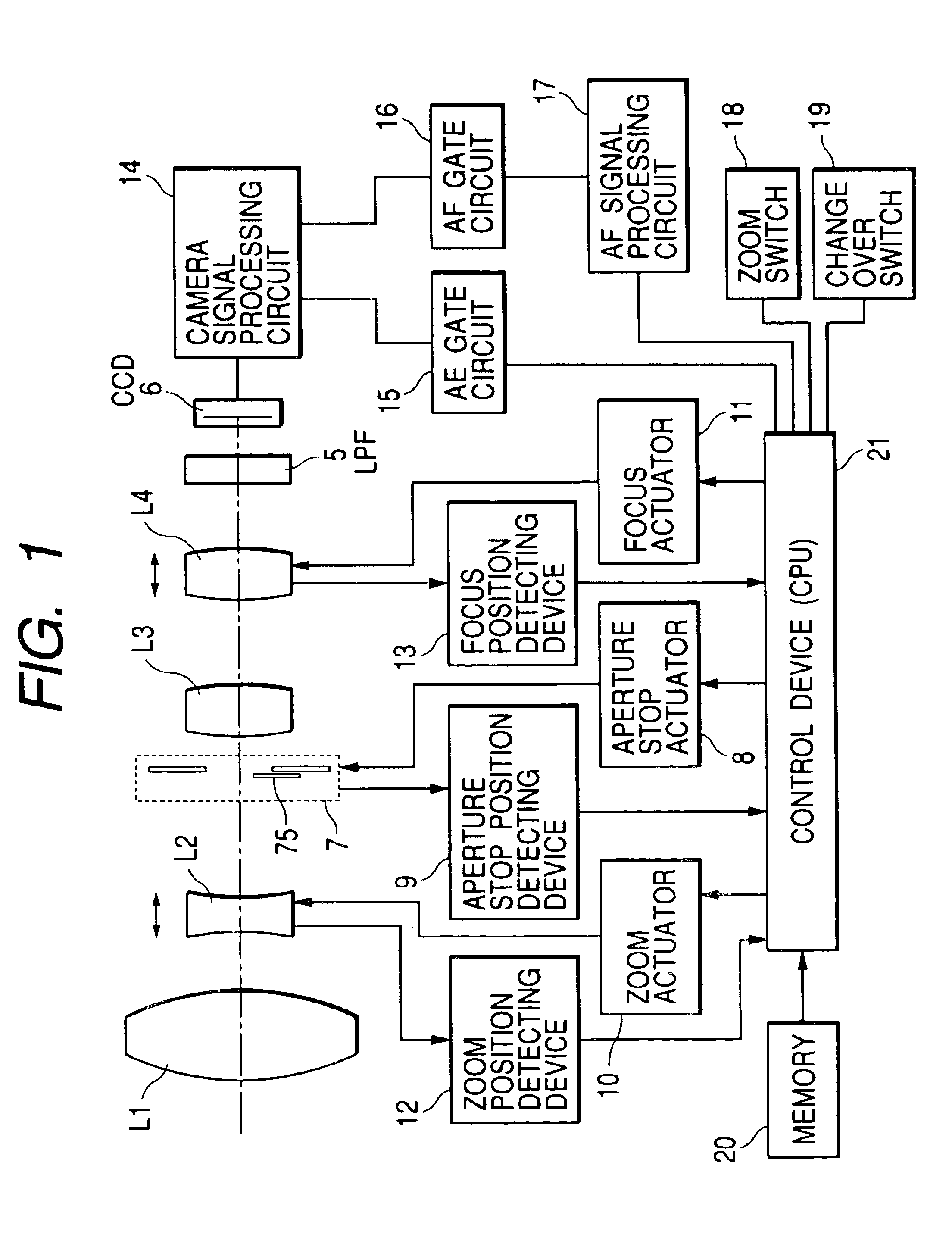
[0053]FIG. 1 is a block diagram of an optical apparatus of first embodiment when applied to a video camera.

[0054]In FIG. 1, symbol L1 denotes a first group lens serving as a fixed convex lens, L2 denotes a concave variator lens for zooming (changing magnification of) an object, L3 denotes a third group lens serving as a fixed convex lens, L4 denotes a convex focus lens for correcting an image surface when zooming an object and adjusting a focus. An optical system is obtained by constituting a rear focus zoom lens (RFZ lens) by the above lenses. Symbol 5 denotes a low pass filter and 6 denotes a solid state image taking device such as a CCD or CMOS. The optical system of these RFZ lenses, members, and an aperture stop unit to be described later are housed in and held by a not illustrated fixed lens tube.

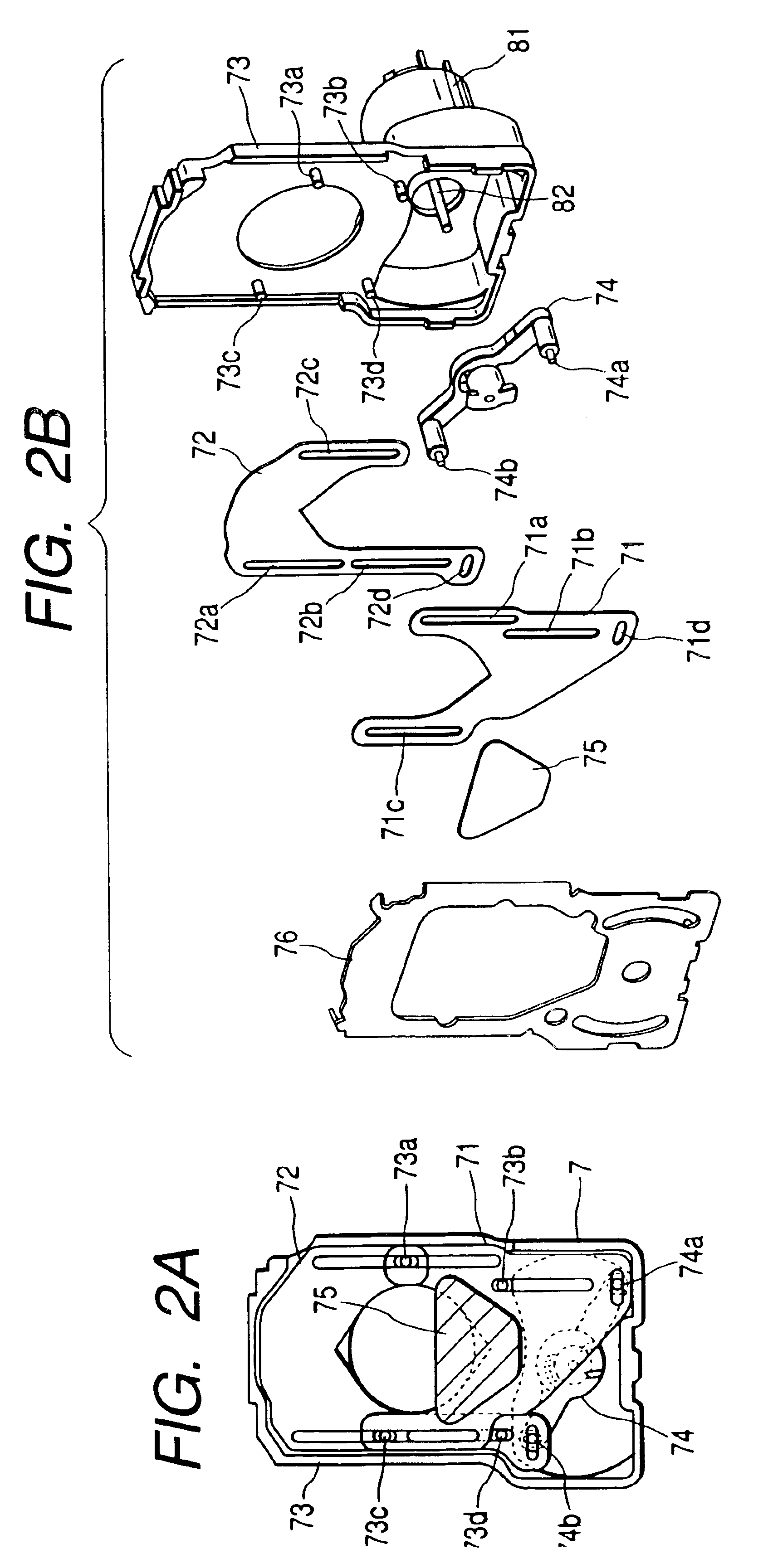
[0055]Symbol 7 denotes an aperture stop unit which is constituted by a galvanometer aperture stop actuator 8 for rotating a magnet rotor due to the voltage applied t...

second embodiment

(Second Embodiment)

[0088]FIG. 8 shows second embodiment of an optical apparatus of the present invention, which is a block diagram when applying the optical apparatus to a video camera and a member common to that in FIG. 1 is provided with the same symbol to omit duplicate description. This embodiment makes it possible to independently drive an ND driving unit 201 having an ND filter by a filter actuator 212 separately from an aperture stop unit 7 by setting the unit 201 after the unit 7 (image surface side of an optical system). In FIG. 8, symbol 211 denotes a position detecting device for detecting the entrance amount (position) of the ND filter (ND filter 204 shown in FIG. 9) into the optical path of the optical system, which is constituted by, for example, a Hall element. The ND filter is driven and controlled so as to enter the optical path by detecting luminous energy and relating the luminous energy to an aperture stop value so as not to be influenced by diffraction when the ...

third embodiment

(Third Embodiment)

[0113]FIGS. 13A and 13B show third embodiment of an optical apparatus of the present invention, which serves as an ND filter change unit of another embodiment of the ND driving unit shown by the block diagram in FIG. 8. Therefore, configurations other than the configuration of the ND filter change unit are the same as those in FIG. 8. FIGS. 13A and 13B are top views of an ND filter change unit which can be manually operated. The ND filter change unit is constituted separately from an aperture stop unit, independently driven, and set to the rear (image surface side) of the aperture stop unit.

[0114]In FIGS. 13A and 13B, symbols 301 and 320 denote filter frames to which ND filters 302 and 321 are bonded and fixed. The ND filers 302 and 321 are constituted so as be inserted into an optical path at shifted positions on the optical path. It is allowed that these ND filters have the same density or different densities and thicknesses of the filters are equal to or differe...


PUM


Abstract

An optical apparatus is disclosed which comprises an optical system provided with a zoom lens for performing zooming by moving along the optical axis and a focus lens for performing correction and focusing at the time of zooming, an imaging device for imaging an optical image supplied from the optical system, a zoom actuator for driving the zoom lens, a focus actuator for driving the focus lens, a zoom position detecting device for detecting the position of the zoom lens, a focus position detecting device for detecting the position of the focus lens, an aperture stop member whose opening diameter changes so as to adjust the luminous energy passing through the optical system a filter member to be freely inserted into or extracted from the optical path of the optical system, an aperture stop state detecting device for detecting the opening state of the aperture stop member, a filter state detecting device for detecting the insertion state of the filter member, a memory storing the movement information on the relation between the position of the zoom lens for keeping a focused state and the position of the focus lens, and a control device for correcting the movement information in accordance with an output of the aperture stop state detecting device and an output of the filer state detecting device and controlling driving of the focus lens.

Description

BACKGROUND OF THE INVENTION[0001]1. Field of the Invention[0002]The present invention relates to an optical apparatus such as a video camera or still camera having a forward / backward movable filter member in an optical path of an image taking optical system.[0003]2. Related Background Art[0004]When image taking an object with a still camera or video camera, if an aperture stop diameter becomes too small though the object is bright, deterioration of image quality due to diffraction and dust image taken due to increase of focal depth become issues. Therefore, to prevent an aperture stop diameter from becoming too small, there are some still cameras or video cameras in which an ND filter is directly set to an aperture stop vane of the aperture stop apparatus of an image taking lens, an aperture stop opening is formed by driving a plurality of aperture stop vanes, and the ND filter integrally set to the aperture stop vane is inserted into the aperture stop opening. Moreover, there are s...

Claims


Application Information

Patent Timeline
Patent Type & Authority Patents(United States)
IPC IPC(8): G02B7/10G02B7/08G03B13/36G02B7/28G03B9/04G03B9/07G03B11/00H04N5/232H04N5/238
CPCG02B7/102H04N5/23212H04N5/23296H04N5/238H04N23/55H04N23/67H04N23/69H04N23/75
Inventor OKADA, TADANORIHORIUCHI, AKIHISA
Owner CANON KK
Why Eureka
Try Eureka