Energy transfer multiplexer

a multiplexer and energy transfer technology, applied in the direction of dc-ac conversion without reversal, process and machine control, instruments, etc., can solve the problems of complex control mechanism of pitch angle, inconvenient maintenance and repair, inability to maintain operation, etc., to increase the ratio of electrical output power, reduce rating, and high efficiency

Active Publication Date: 2005-08-02
SPELLMAN HIGH VOLTAGE ELECTRONICS
View PDF5 Cites 18 Cited by
  • Summary
  • Abstract
  • Description
  • Claims
  • Application Information

AI Technical Summary

Benefits of technology

[0019]For example, the electro-mechanical energy conversion system of the present invention may convert wind energy into an electrical power output to a polyphase electric power grid operating at a system frequency comprising a variable speed generation system such as a turbine for converting the wind energy into mechanical energy and a generator coupled to the turbine to drive the rotor to create power in the stator to supply electrical power to the power grid. The generation system also includes control means for varying the rotor speed in response to the power output and the wind energy to increase the ratio of the electrical output power to the wind energy input.
[0020]Such an electro-mechanical energy conversion system operates at high efficiency regardless of variable resource conditions by controlling the rotor speed. Thus, the electro-mechanical energy conversion system can operate at substantially reduced rating. Thus, the equipment and operating costs are significantly lower than those of existing systems.

Problems solved by technology

Unfortunately, such pitch angle control mechanisms are complex and costly to manufacture, maintain and repair.
Unfortunately, such systems are inefficient, relatively expensive, difficult to maintain operation and relatively unreliable as an electricity source.

Method used


Image

  • Energy transfer multiplexer
  • Energy transfer multiplexer
  • Energy transfer multiplexer

Examples


Embodiment Construction

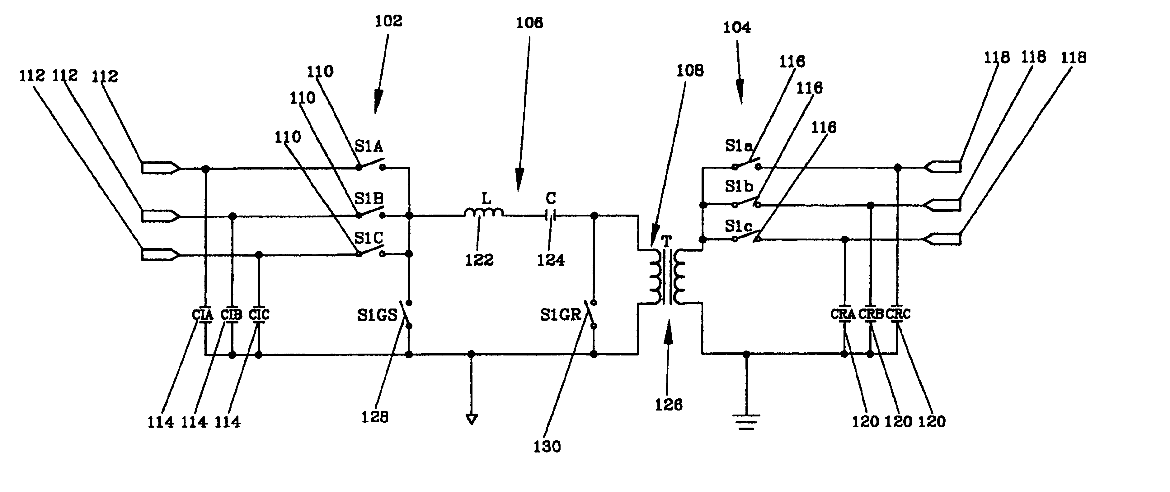
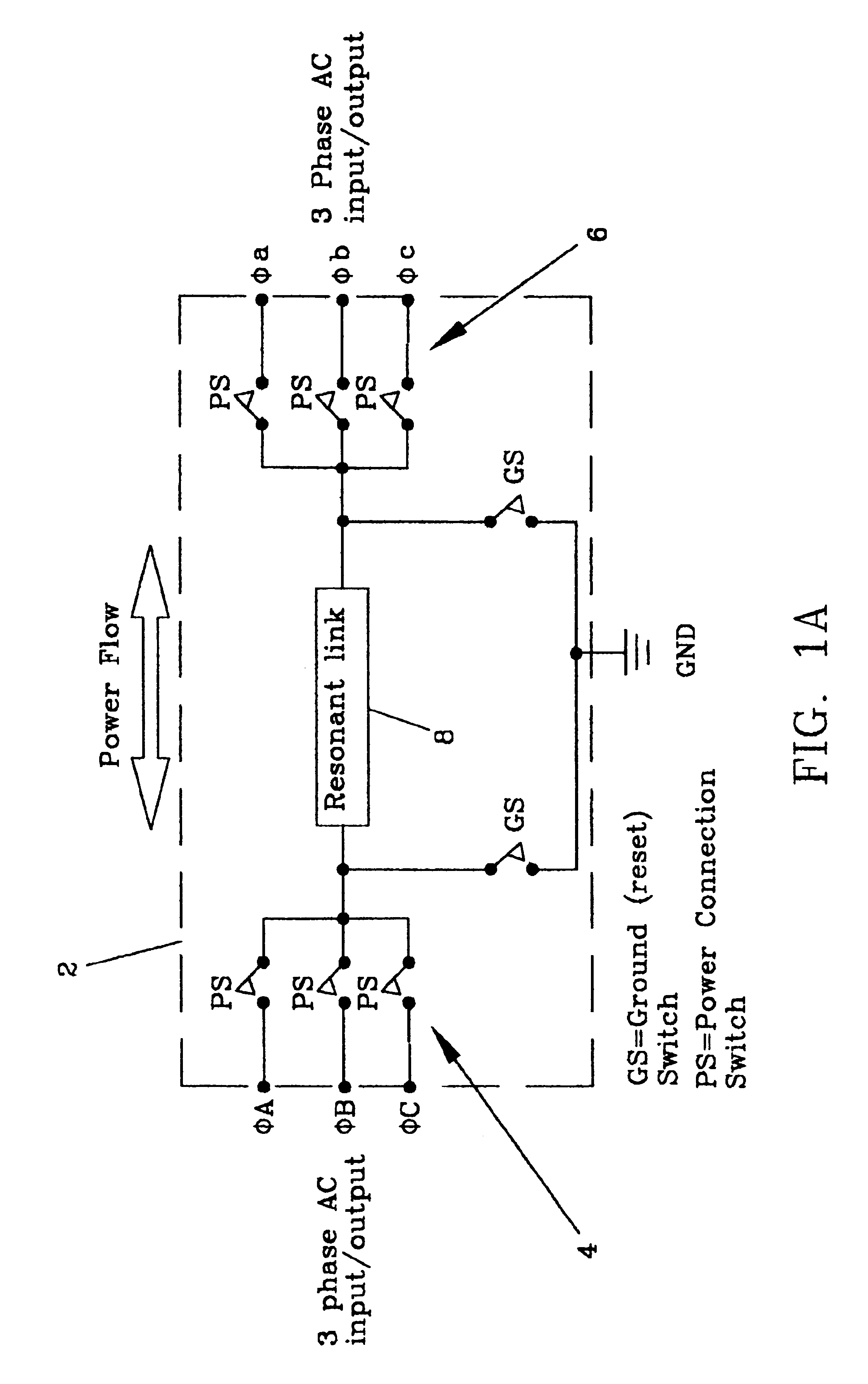
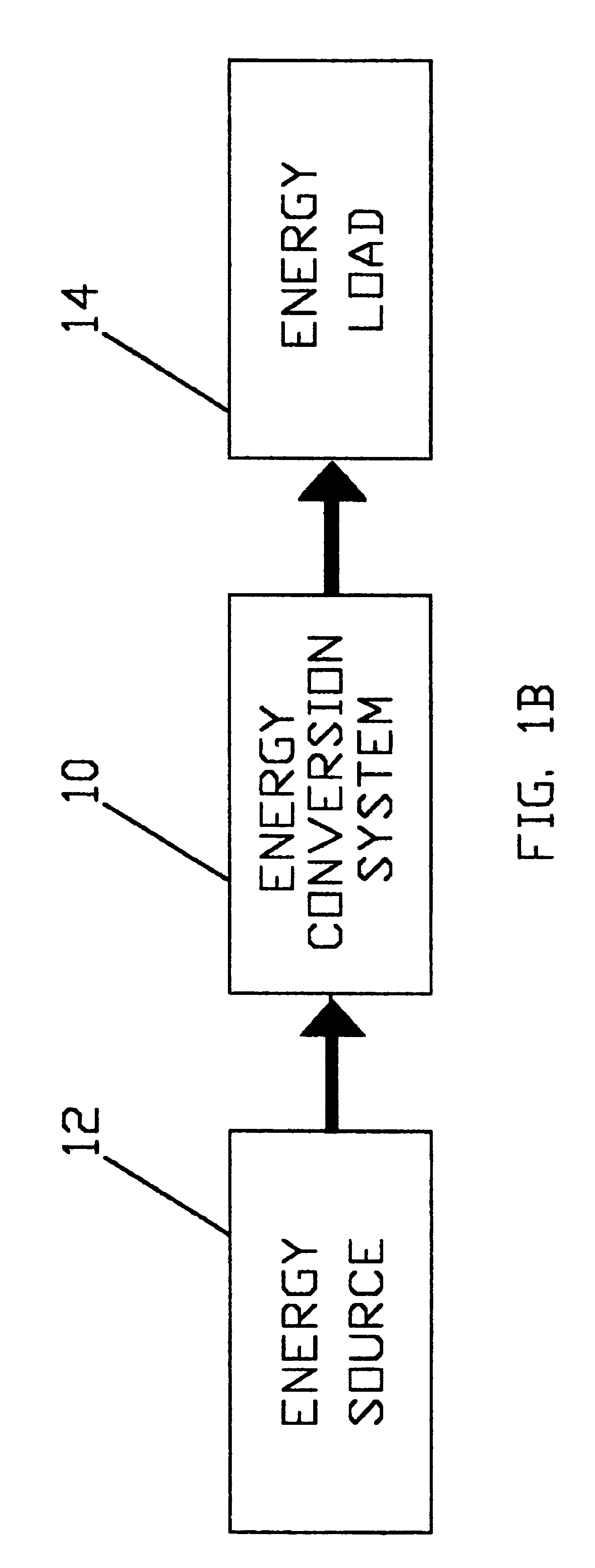
[0049]The present invention relates to an energy transfer multiplexer to selectively link the flow of energy from an energy source to an energy load. The energy transfer multiplexer may be configured for use with an electro-mechanical conversion system as described hereinafter.

[0050]Such an electro-mechanical energy conversion system may be configured to operate as a generator or motor. As a generator, the electro-mechanical energy conversion system can convert mechanical energy from wind turbines, hydro turbines, steam turbines, internal combustion engineers, fly wheels and the like to generate electrical energy to power an electrical power grid, rural power, electric boats, industrial pumps and the like.

[0051]The electrical energy can also be converted and stored in the form of hydrogen storage, batteries or compressed air for future use. Likewise, as a motor, the electro-mechanical energy conversion system can convert electrical energy from an electrical power source to power a w...


PUM


Abstract

An energy transfer multiplexer to control the flow of power or energy between an energy source and an energy load comprising a bi-directional inverter including a first bank or plurality of switches or first plurality of energy transfer control points and a second bank or plurality of switches or second plurality of energy transfer control points operatively coupled by a series resonant transfer link to selectively control the direction of power or energy flow between the first and second bank or plurality of switches or the first and second plurality of energy transfer control points.

Description

CROSS REFERENCE APPLICATION[0001]This is a non-provisional patent application of provisional patent application Ser. No. 60 / 442,633 filed Jan. 23, 2003.BACKGROUND OF THE INVENTION[0002]1. Field of the Invention[0003]An energy transfer multiplexer to selectively convert and transfer energy from an energy source and an energy load.[0004]2. Description of the Prior Art[0005]Seemingly limitless electro-mechanical systems and devices have been devised to convert electrical energy to mechanical energy or vice versa.[0006]In efforts to reduce dependency on fossil fuels, countless generator systems to convert mechanical to electrical energy including various wind power systems or wind turbines have been developed. Such systems generally include a shaft-mounted turbine to drive an electrical generator. To operate the generator at optimum speed for maximum power output, the wind turbine must produce a relatively constant torque or speed despite changes in wind speed and wind direction. Genera...

Claims


Application Information

Patent Timeline
Patent Type & Authority Patents(United States)
IPC IPC(8): H02M5/02H02M5/27H02M5/297H02M7/48
CPCH02M5/272H02M5/297H02M7/4826Y02B70/145Y02B70/10
Inventor SKEIST, S. MERRILLBAKER, RICHARD H.
Owner SPELLMAN HIGH VOLTAGE ELECTRONICS
Why Eureka
Try Eureka