Reactor core and method for operating nuclear reactor

a reactor core and reactor technology, applied in the field of reactor cores, can solve the problems of nuclear non-proliferation, the concentration of burnable poison cannot be raised above a certain level, and the difference in the void coefficient between the first and second halves of the actual operating period cannot be markedly different,

a reactor core and reactor technology, applied in the field of reactor cores, can solve the problems of nuclear non-proliferation, the concentration of burnable poison cannot be raised above a certain level, and the difference in the void coefficient between the first and second halves of the actual operating period cannot be markedly different,

US6925138B2Inactive Publication Date: 2005-08-02KK TOSHIBA

Image

  • Reactor core and method for operating nuclear reactor
  • Reactor core and method for operating nuclear reactor
  • Reactor core and method for operating nuclear reactor

Examples


Embodiment Construction

[0051]Embodiments of the present invention will now be described with reference to the accompanying figures.

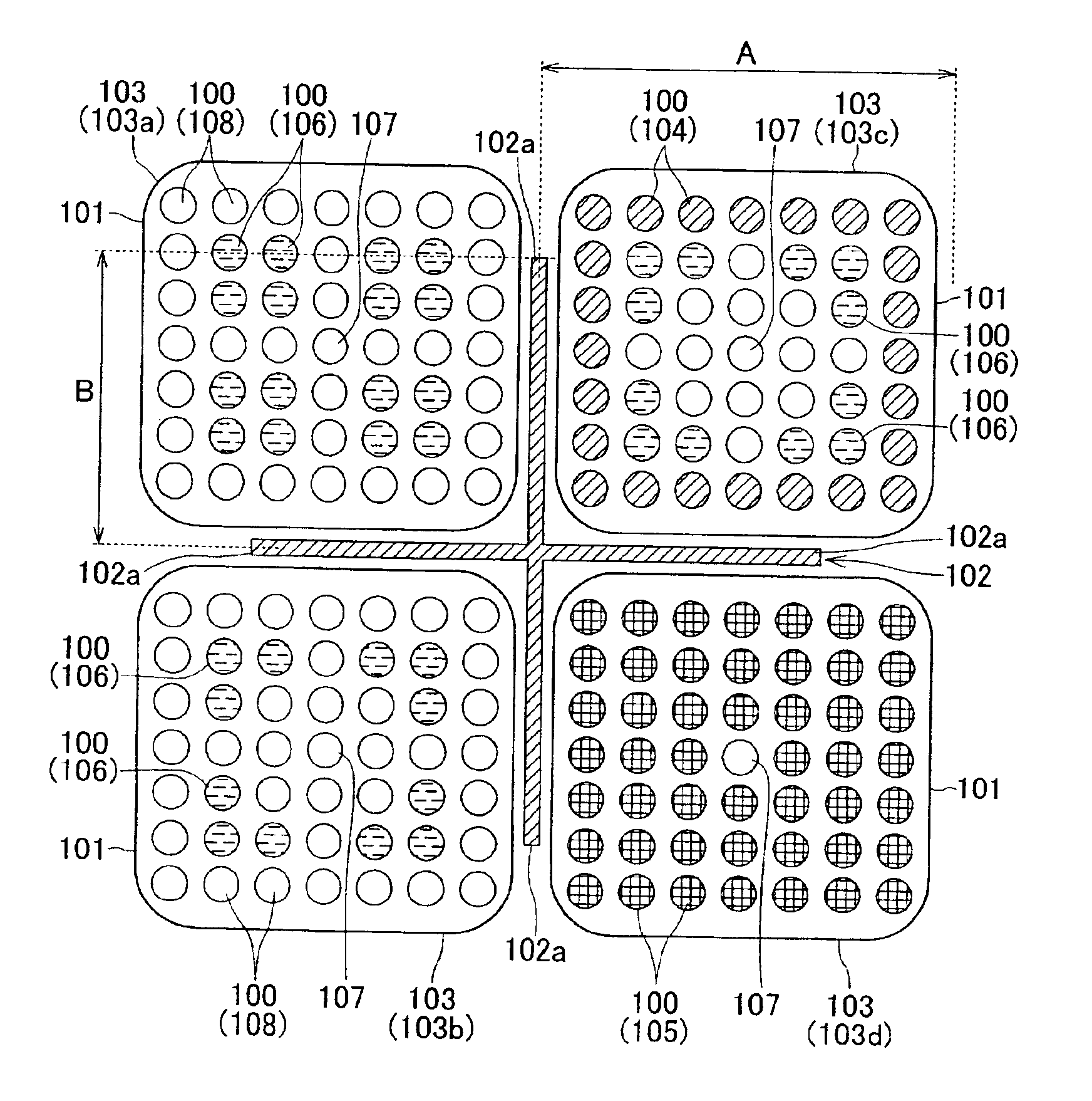
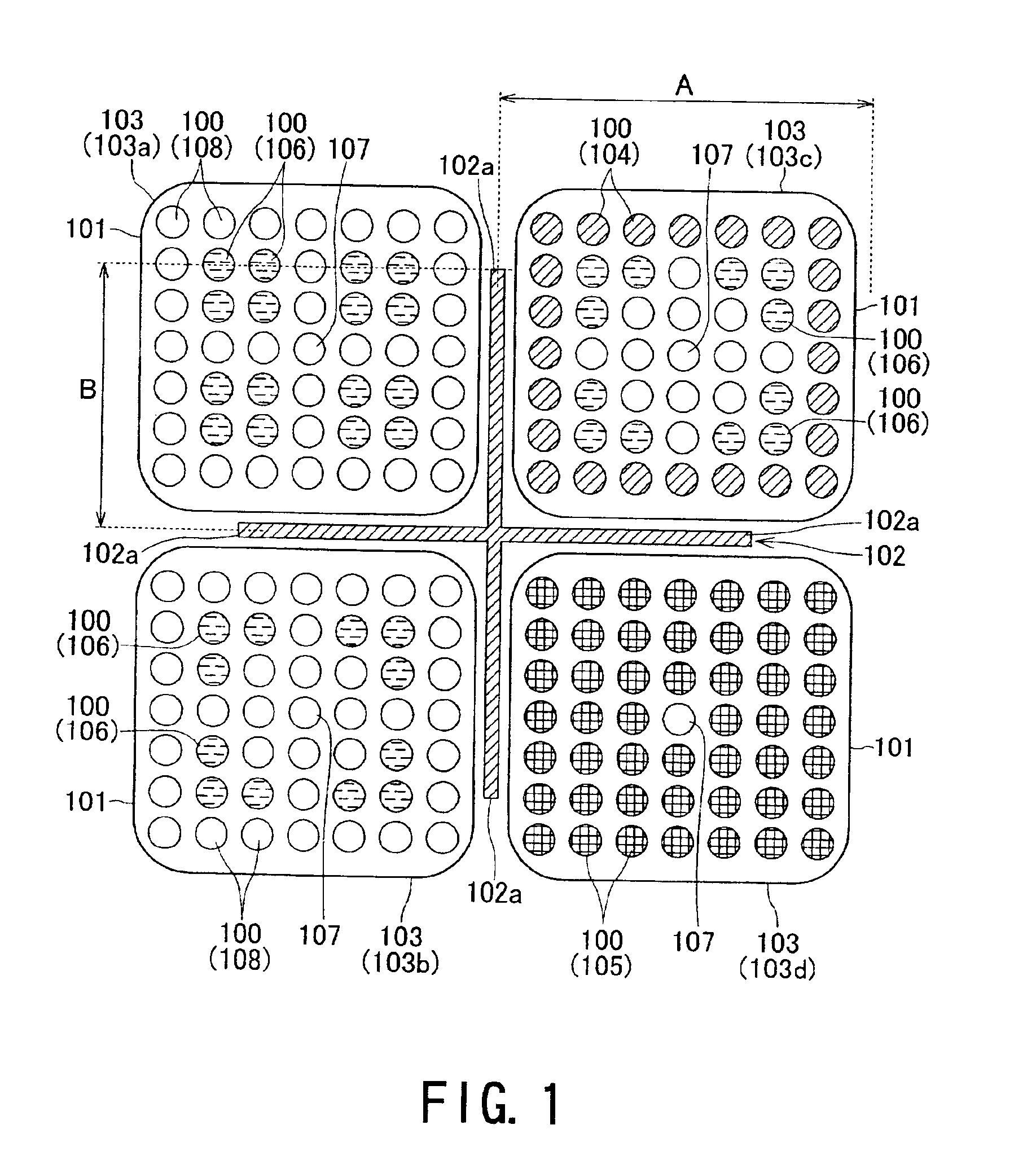
[0052]FIG. 1 is an enlarged plate cross-sectional view of fuel assemblies and control rods designed to illustrate the structure of a reactor core. FIG. 1 shows a case in which four different types of fuel assemblies are loaded at the same locations in the reactor core, but this arrangement is shown solely for the sake of convenience, and in actual conditions the fuel assemblies can be appropriately combined and loaded in accordance with their position inside the core.

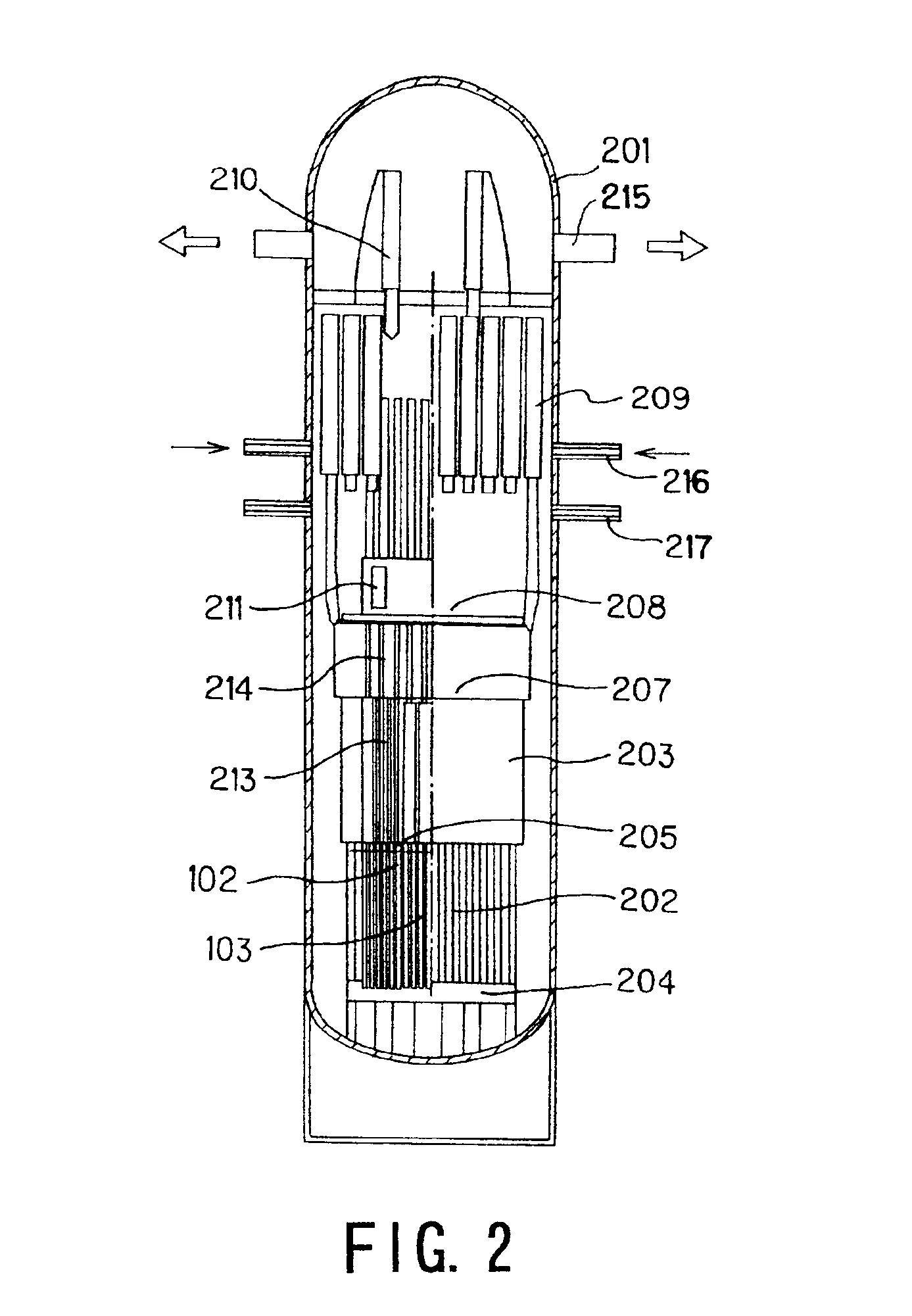
[0053]FIG. 2 is a longitudinal schematic cross-sectional view showing the structure of a reactor pressure vessel for a boiling-water reactor in which the above-described core is used. FIG. 3 is a diagram illustrating the operation of the present invention.

[0054]The structure of the reactor pressure vessel 201 for the boiling-water reactor as a light water reactor configured in accordance with the present embodimen...


PUM


Abstract

The present invention is to provide a reactor core that allows a nuclear plant to continuously operate for a long term period, for example 15 years or longer, without requiring any fuel exchange, reduces the duration and number of maintenance steps involved in regular plant inspections, markedly improves plant availability and economic efficiency, and is effective in terms of nuclear nonproliferation.A plurality of fuel assemblies 103, themselves obtained by arranging fuel rods 100 and water rods 107 in square lattices, are arranged in a square lattice at a certain pitch. The blades 102a of a cross-shaped (cruciform) control rod 102 in a cross section are inserted into four adjacent spaces formed by four fuel assemblies 100 facing each other. A value of 0.06 cm−1 or greater is selected for the ratio (B / S) of the width (B) of each blade on the cruciform control rod 102 and the surface (S) of the fuel lattice defined by the surface area of a square whose side is equal to the pitch between the fuel assemblies 103.

Description

BACKGROUND OF THE INVENTION[0001]The present invention relates to a reactor core used in a boiling-water reactor and to a method for operating a nuclear reactor, and more particularly to a reactor core capable of operating in a sustained manner for a long-term period, such as 15 years or longer, without fuel exchange, and to a method for operating a nuclear reactor.[0002]The boiling-water nuclear power plants currently in use on a commercial basis have a maximum plant operating cycle of about 2 years, and at the end of each operating cycle the plants are shut down, the vessel cover of the reactor pressure vessel is opened, and a regular (periodic) inspection and fuel exchange are carried out. In this case, spent fuel is transported to and stored in a spent fuel storage pool disposed on the upper floor (section) of the reactor building, so the reactor well is filled with water pumped from a condensation storage tank or pressure suppression pool. The level of the fuel remaining in the...

Claims


Application Information

Patent Timeline
02 Aug 2005
Publication
US6925138B2
IPC
G21C1/08; G21C5/00; G21C7/00; G21C7/04; G21C7/113; G21C7/08; G21C1/00; G21C3/328; G21C7/14; G21C7/24; G21C7/27
CPC
G21C1/084; G21C5/00; G21C7/04; G21C7/113; G21Y2002/201; G21Y2002/304; G21Y2002/40; G21Y2004/30
Inventors
NAKAMARU, MIKIHIDE; HEKI, HIDEAKI