Plasma etching method having pulsed substrate electrode power

a technology of pulsed substrate electrodes and etching methods, which is applied in the direction of plasma techniques, decorative arts, electric discharge tubes, etc., can solve the problems of low directionality, partially deviating, and incident ions can also have a relatively significant degree of scattering, and achieve high repetition rates.

Inactive Publication Date: 2005-08-09
ROBERT BOSCH GMBH
View PDF7 Cites 18 Cited by
  • Summary
  • Abstract
  • Description
  • Claims
  • Application Information

AI Technical Summary

Benefits of technology

[0014]In comparison with the related art, the plasma etching method according to the present invention has the advantage that with this method, the pulse times and interval times of the coupled, high-frequency-pulsed high-frequency power can be significantly shortened, and pulse operation having a high repetition rate in the 100 kHz range can be implemented.

Problems solved by technology

However, as a result, the incident ions can also have a relatively significant degree of scatter with respect to their direction and can partially deviate from the desired, vertical incidence or can be slightly deflected, i.e., their directionality is low.
Such deviations in the directionality of the incident ions then correlates to more difficult profile verification of the produced etching profile.
At the same time, as the ion energy increases, so does the danger of so-called “grass formation” on the etching ground, i.e., the process window for a reliable etching process without grass formation is limited.
To date, this requirement for a “notch-resistant” process, therefore, conflicts with a “grass-resistant” process.
On the whole, in the known methods under the marginal conditions of a “grass-free” etching ground and a sufficient suppression of “notching,” the employable high-frequency peak pulse powers and, as such, the ion energies, i.e., the directionality of the ion incidence, is, therefore, restricted, thereby resulting, to date, in the process window, i.e., the usable process parameters, being restricted in an undesired manner.
Due to the grass formation, this restriction of the process window has a particularly disruptive effect when high-rate etching processes are to be carried out, since, as such, the range of allowable process pressures is restricted in an upward direction.

Method used


Image

  • Plasma etching method having pulsed substrate electrode power
  • Plasma etching method having pulsed substrate electrode power
  • Plasma etching method having pulsed substrate electrode power

Examples


Embodiment Construction

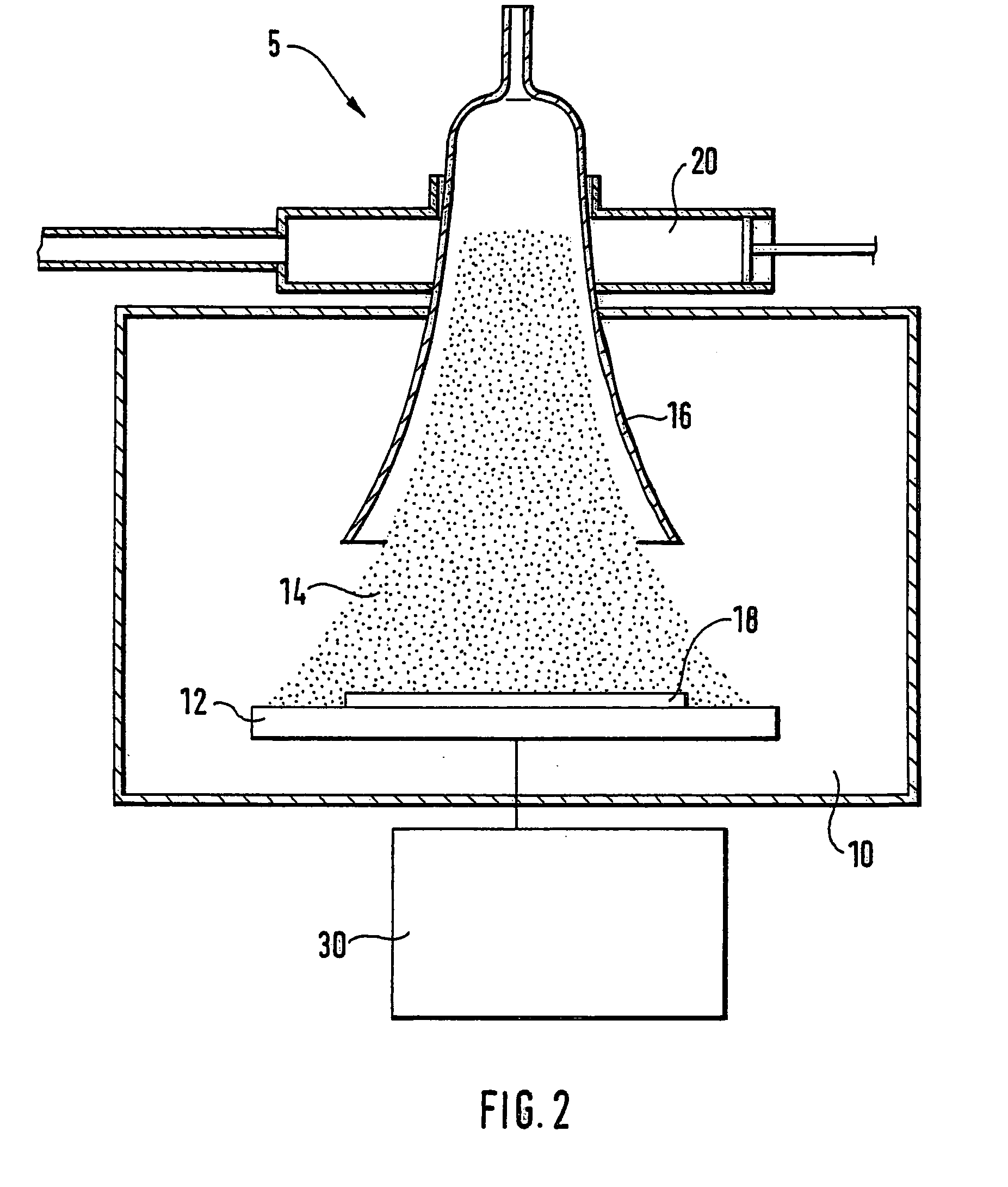
[0037]FIG. 2 shows a plasma etching system 5 principally known from German Patent No. 42 41 045 C2 or German Patent No. 197 06 682 A1, for implementing an anisotropic plasma etching method. For this purpose, a substrate electrode 12 is provided in an etching chamber 10 with an etching body 18, which is situated on the substrate electrode and is a silicon wafer in the explained example. Furthermore, substrate electrode 12 is electrically connected to a generator unit 30. Moreover, a resonator 20 is provided via which a plasma 14 is produced in etching chamber 10 in the region of a surfatron 16. The explained exemplary embodiment is, however, not limited to such a system configuration. In particular, an ICP plasma source (inductively coupled plasma) or an ECR plasma source (electron cyclotron resonance) is also suitable for this purpose.

[0038]A high-density plasma source produces a plasma 14, which is made of neutral radicals and electrically charged particles (ions), the ions being a...


PUM

PropertyMeasurementUnit
high-frequency poweraaaaaaaaaa
frequencyaaaaaaaaaa
frequencyaaaaaaaaaa

Abstract

A method is proposed for etching patterns in an etching body (18), in particular cut-outs in a silicon body (18) exactly defined in a lateral manner, using a plasma (14). In this context, a high-frequency-pulsed high-frequency power is at least temporarily coupled into the etching body (18) via an at least temporarily applied high-frequency a.c. voltage. This coupled, high-frequency-pulsed high-frequency power is further modulated at a low frequency, in particular clocked. The proposed method opens a wide process window for varying the etching parameters in the implemented plasma etching process, and is especially suitable for etching patterns in silicon using high mask selectivity and high etching rates for simultaneously minimized charge effects, in particular with respect to notching on the dielectric boundary surface.

Description

FIELD OF THE INVENTION[0001]The present invention relates to a method for etching patterns in an etching body using a plasma.BACKGROUND INFORMATION[0002]Anisotropic plasma etching methods are known, for example, from German Patent No. 197 06 682 A1 or German Patent No. 42 41 045 C2, in which, in each case, a plasma of neutral radicals and electrically charged particles is produced via a high-density plasma source, the particles being accelerated by a bias voltage source in the direction of a substrate electrode carrying the wafer to be processed. In this context, a directed etching process is achieved by the preferential direction of the incident ions.[0003]Furthermore, high-frequency generators having a carrier frequency of 13.56 MHz are typically used as the bias voltage source that produces the electrical voltage for accelerating the ions from the plasma in the direction of the substrate electrode. In this context, the high-frequency generator is adjusted by an LC network (“match...

Claims


Application Information

Patent Timeline
Patent Type & Authority Patents(United States)
IPC IPC(8): H01J37/32H01L21/02H01L21/3065H05H1/46H01L21/302
CPCH01J37/32082H01J37/32155H01J37/32706H01L21/3065H01L21/30655
Inventor LAERMER, FRANZSCHILP, ANDREA
Owner ROBERT BOSCH GMBH
Why Eureka
Try Eureka