If, however, during the read operation, the inversion layer is not strong enough to prevent the current flow through the channel, than the bit will be read as a “1”, and the
cell will fail program
verification.
However, this strategy will not meet the second requirement due to many process and environmental parameters that affect the programming rate and its variations.
The wide variation of programming speeds creates problems during programming of
memory cell arrays.
When an improper programming
algorithm is used, some cells may receive too high programming voltages or may be programmed for too long.
1), creating reliability problems due to the degradation of the quality of the product.
Furthermore, continuing to apply
high voltage pulses once the unit cells have already reached the programmed level wastes power and creates a power dissipation problem.
Moreover, as to be described below, in multi-level floating gate products, over-programming can lead to information read failures.
When a cell is over-programmed, the
resultant threshold voltage may overshoot the desired region, thus leading to a read error or failure.
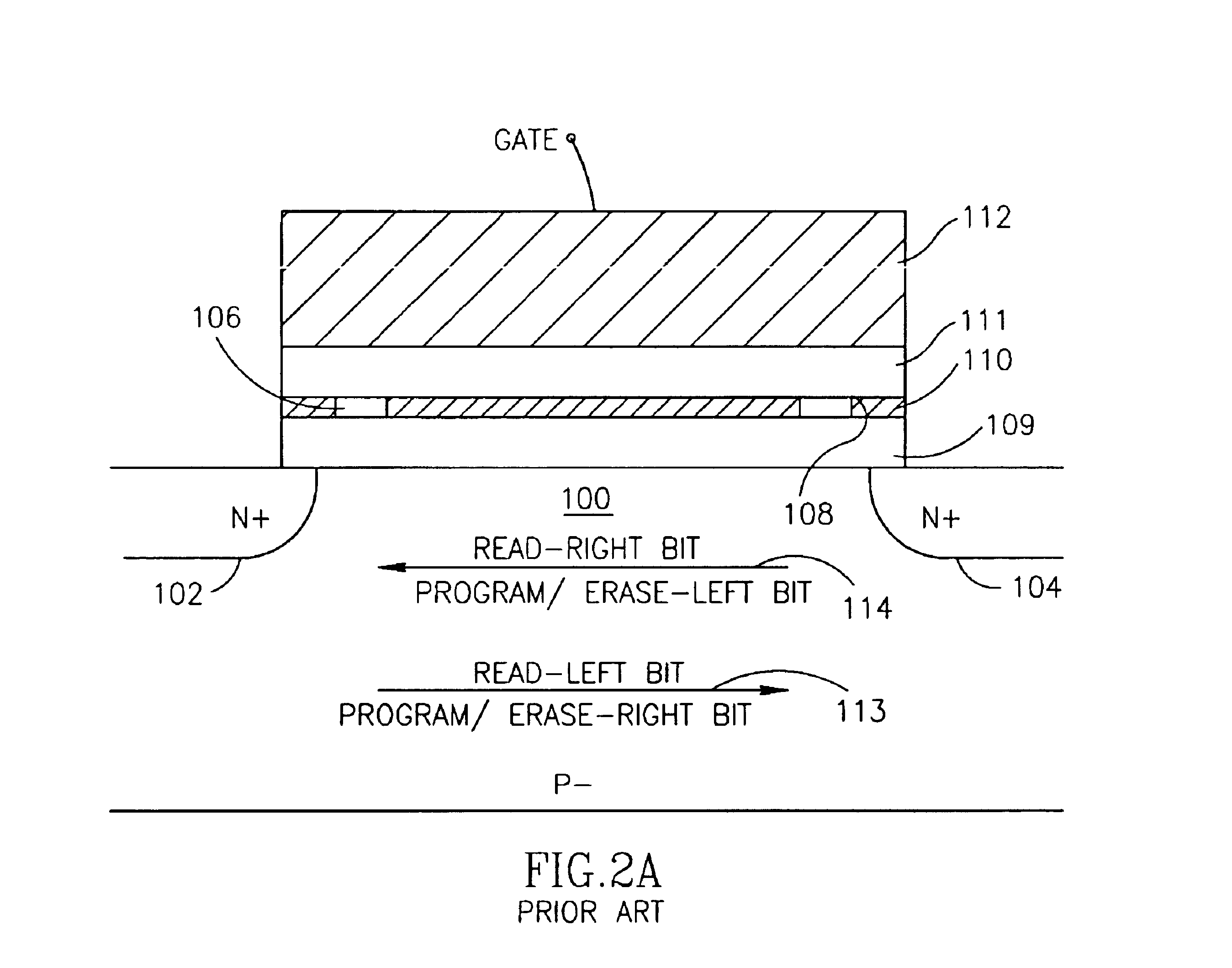
Further problems arise when programming both bits of multi-bit memory cells, such as the two-bit NROM cell.
In NROM cells, in addition to the stated problems connected with breakdown of the
oxide layer and unnecessary dissipation of power, over-programming creates different problems.
As explained below in connection with FIG. 6, over-programming results in quality deterioration and reliability degradation, as well as read failures in two-bit cells.
Applicants note that
tail 44, which is further from the
bit line than the bulk of the trapped charge, is generally not removable during erasure and thus, reduces the ability of the NROM cell to withstand a large number of program and erase cycles.
Furthermore, the accumulation of trapped
negative charge far from the junction increases the
threshold voltage level, which affects the reverse read, making it difficult to distinguish the first bit from the second bit and creating read failures.
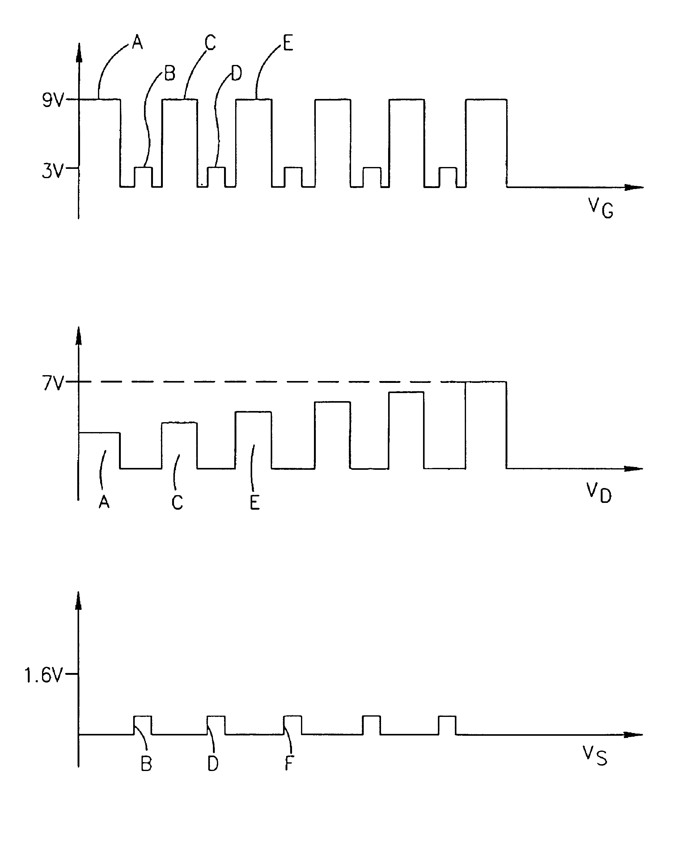
Unfortunately, prior art methods of gradually increasing the programming
gate voltage VG are not effective for NROM cells, and tend to produce the following two problems:1. In NROM products, increases in the
gate voltage VG do not linearly correlate to increases in the
threshold voltage VTH, and the effect of the increases varies from cell to cell.
This causes a lack of precise programming control, and an incurred risk of over programming.2. In order to ensure a reasonable
yield rate, meeting the programming rate requirement, the drain voltage VD potential must be high, creating trapped charge regions distant from the junction.
The above two problems result in reduction in the endurance of the product, increase in the
charge loss and reduction in yield.
As a further complication, the reduction in VDS increases the programming time exponentially.
Reduction in the incremental increase of the
gate voltage VG can alleviate part of the control problem, but it will dramatically increase the programming time.
Low gate voltage VG results in
cycling degradation.
Further increases in gate voltage VG, such as over 10V, require special processes and put severe limitations on the scaling of the ONO thickness due to charging by tunneling.
The second problem noted above (high drain voltage VD) creates even more severe limitations on the stepped gate voltage VG approach.
Accordingly, the
resultant product is the undesirable
tail 44, which drastically reduces the product's endurance.
Hence, due to the first problem noted above, using the gate voltage VG as a dynamic parameter for controlling programming is very limited in range.
In conclusion, in NROM cells, stepping the programming gate voltage VG does not provide tight programming control and is not effective in preventing over-programming and eventual degradation of the product's quality.
As can be understood from the above, when prior art programming algorithms are applied to the NROM cell, they do not sufficiently provide the abilities to produce increased programming speed while maintaining tight programming control.

