Method for treating waste by hydrothermal oxidation

a hydrothermal oxidation and waste technology, applied in the direction of sludge treatment by oxidation, supercritical condition processes, bulk chemical production, etc., can solve the problems of affecting affecting and not allowing the optimal decomposition of organic matter, etc., to achieve the effect of improving the total energy balance of the process, improving the reaction time and thus the reaction yield

Inactive Publication Date: 2005-08-16
INNOVEX
View PDF9 Cites 19 Cited by
  • Summary
  • Abstract
  • Description
  • Claims
  • Application Information

AI Technical Summary

Benefits of technology

[0022]According to yet another specific embodiment of the invention, said tubular body exhibits a plurality of portions with cross sections of different sizes. This configuration makes it possible to alternately insert narrower portions of tubular body, in which portions the oxidizing composition is injected, and wider portions, where the oxidation reaction takes place. Thus, the residence time of the reaction mixture in the wider portions is greater, which makes it possible to increase the reaction time and thus the reaction yield between each injection of oxidizing composition.
[0023]According to an advantageous arrangement, a portion of the thermal energy produced by said oxidation is imparted to said aqueous effluent, taken under the initial pressure and temperature conditions, in order to bring it to said temperature T1. In that way, it is not necessary to provide additional heating means to bring said aqueous effluent from the initial temperature to

Problems solved by technology

On the other hand, when the oxidizing agent is introduced before having begun to compress and heat the mixture, hot spots can appear in the reactor.
In addition to the fact that the appearance of these hot spots can affect the walls of the reactor, the poor distribution of the oxidizing agent in the reaction medium leads to a mediocre yield of the reaction for the decomp

Method used


Image

  • Method for treating waste by hydrothermal oxidation
  • Method for treating waste by hydrothermal oxidation
  • Method for treating waste by hydrothermal oxidation

Examples


Embodiment Construction

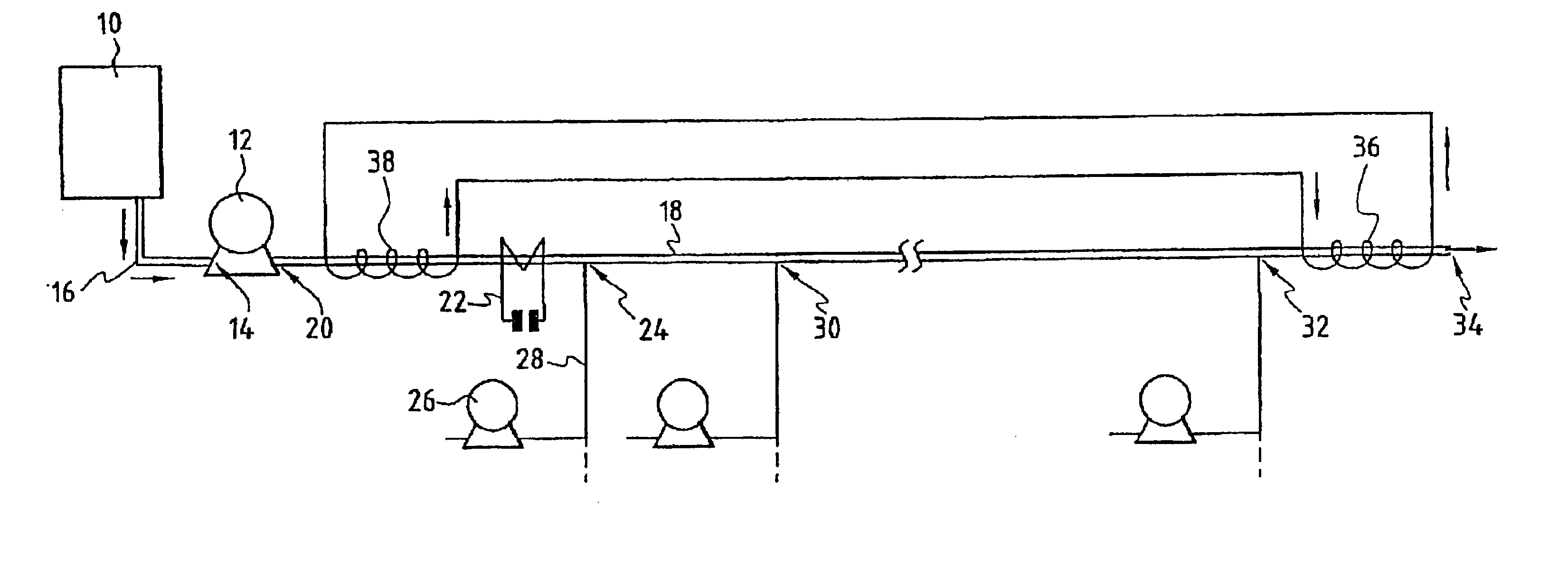
[0045]Reference will be made to FIG. 1 in describing the plant for implementation of the process for the oxidation of the organic substances present in the aqueous effluent.

[0046]The aqueous effluent comprising the organic substances to be converted is stored upstream of the plant for implementation of the process in a tank 10. The aqueous effluents are generally composed of industrial or municipal sludge or of aqueous liquors resulting from industrial processes.

[0047]A pump 12, the entry orifice 14 of which is connected via a pipe 16 to the lower end of the tank 10, is capable of pumping the aqueous effluent and of injecting it under pressure into a tubular body 18 at its inlet orifice 20. The pump 12 is capable of injecting the aqueous effluent into the tubular body 18 under a pressure of greater than 22 MPa, which corresponds substantially to the critical pressure of water.

[0048]The tubular body 18 is equipped with a thermoelectric generator 22 which at least partially surrounds ...


PUM


Abstract

A method for oxidizing organic matter contained in an aqueous effluent and an installation for implementing the method. The method comprises the following steps: injecting into a tubular body the aqueous effluent; bringing the aqueous effluent to a pressure P1, corresponding to the critical pressure of the aqueous effluent; bringing the aqueous effluent to a temperature T1; and injecting into the tubular body at n points spaced apart from one another, n fractions of at least an oxidizing composition, so that a portion of the thermal energy produced by the oxidation reaction increases the temperature of the reaction mixture from said temperature T1 to temperature T2>T1 according to an increasing curve, whereby the organic matter is oxidized, the reaction mixture continuously developing from a sub-critical liquid state to the supercritical domain.

Description

CROSS REFERENCE TO RELATED APPLICATION[0001]This is the 35 USC 371 national stage of international application PCT / FR01 / 02782 filed on Sep. 7, 2001, which designated the United States of America.FIELD OF THE INVENTION[0002]The present invention relates to a process for the hydrothermal oxidation of waste, in particular but not exclusively organic substances present in aqueous effluent, and to a plant intended for the implementation of said process.[0003]Applications of the invention are in particular, but not exclusively, the conversion of the organic substances present in low amounts in aqueous effluents originating in particular from food processing industries. These aqueous effluents may also comprise dissolved salts. The organic substances are converted to gases capable of being incinerated to provide energy or to gases capable of being released into the atmosphere without danger.BACKGROUND OF THE INVENTION[0004]Processes for the conversion of organic waste present in an aqueous...

Claims


Application Information

Patent Timeline
IPC IPC(8): B01J19/24B01J3/04B01J19/00B01J3/00C02F1/72C02F11/08C02F1/78C02F11/06C02F1/04C02F1/74
CPCB01J3/008B01J3/042B01J19/2415C02F1/72B01J2219/0009C02F11/086B01J2219/00162C02F1/722C02F1/78B01J2219/00135Y02P20/54
Inventor CANSELL, FRAN.CEDILLA.OIS
Owner INNOVEX
Why Eureka
Try Eureka