
Optical microscopy and its use in the study of cells

a technology of optical microscopy and cell, applied in the field of optical microscopy and its use in the study of cells, can solve the problems of limited resolution by diffraction to about 200, 250 nm, and is not possible to use an electron microscope to study living cells, so as to reduce damage and limit light exposure

Inactive Publication Date: 2005-08-16
IONSCOPE
View PDF15 Cites 14 Cited by
  • Summary
  • Abstract
  • Description
  • Claims
  • Application Information

AI Technical Summary

Benefits of technology

[0011]Use of the novel apparatus allows quantitative, high-resolution characterisation of the cell surface and the simultaneous recording of topographic and optical images. A particular feature of the method is a reliable mechanism to control the distance between the probe and the sample in liquid, e.g. physiological buffer.
[0014]By means of the invention, it is possible to image the cell surface in a single scan, by using the probe to keep the cell surface in the confocal volume of the microscope. For biological imaging of live cells, the exposure of light can be limited, thereby minimising damage and overcoming the problem of intense near field light sources used in SNOM. Although the cell may alter shape, this is not a problem in this surface confocal mode, since imaging is always at the surface.

Problems solved by technology

However, the resolution is limited by diffraction to about 200–250 nm.
Hence, it is not possible to use an electron microscope to study living cells.
However, while it is straightforward to fabricate probes with smaller apertures, achieving smaller tip-sample separations in liquid (<60 nm) is difficult because of the problems in obtaining a reliable method of controlling the probe-sample distance.
This is due to damping of the oscillations of the probe used in the feedback mechanism.

Method used


Image

  • Optical microscopy and its use in the study of cells
  • Optical microscopy and its use in the study of cells
  • Optical microscopy and its use in the study of cells

Examples


example 1

[0033]SICM probes are fabricated by pulling borosilicate glass microcapillaries with outer and inner diameters of 1.00 mm and 0.58 mm respectively, using a laser-based micropipette puller (Model P-2000, Sutter Instrument Co., San Rafael, Calif., USA). This reproducibly and easily produces probes with conical taper lengths and apex diameters of 200 nm, 400 nm and 1.0 μm, respectively.

[0034]Three-dimensional and high precision movement of the probe relative to the sample is achieved using a piezo-translation stage (Tritor 100, Piezosystem Jena, Germany) on which the SICM probe is mounted. The stage has a range of 100 μm in the x, y and z directions, so that scanning over biological samples, with features that scale up to 30–50 μm, is made possible. The high voltage required for deformation of the piezo-ceramic material that facilitates the stage's movement is provided by high voltage amplifiers (Piezosystem Jena, Germany). These amplifiers respond to appropriate signals generated by t...

example 2

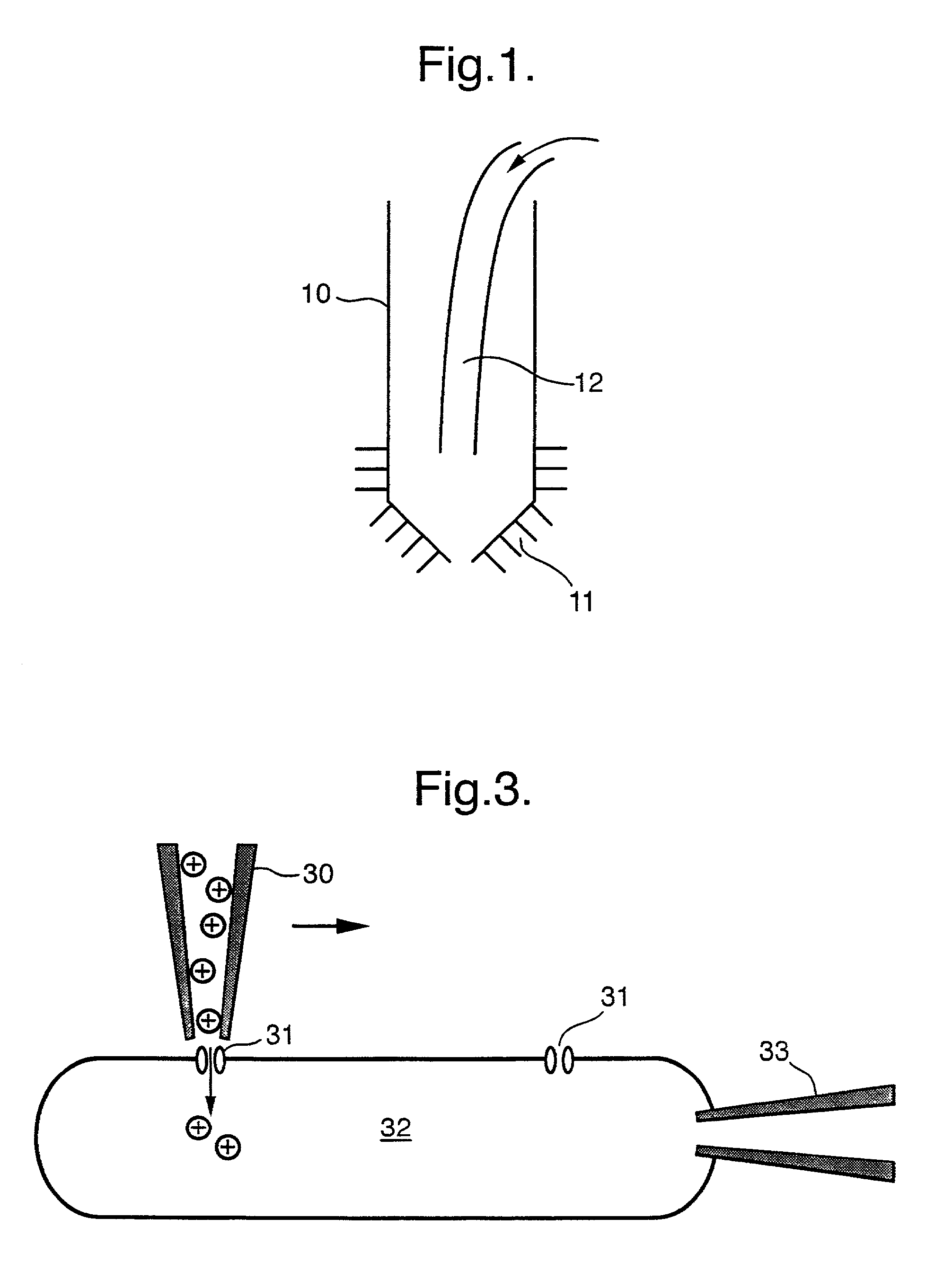
[0041]This Example again illustrates the focal, highly localized application of ions, agonists, or other agents to a membrane during a scan via the microscope micropipette. Monitoring the electrical response of the cell is conducted with a patch-clamp micropipette. This arrangement is illustrated schematically in FIG. 3.

[0042]More particularly, FIG. 3 shows schematically a scanning micropipette 30 whose tip is adjacent to an ion channel 31 in a cell 32. A patch clamp micropipette 33 provides ion channel current recording.

[0043]This Example investigates the distribution of ATP-regulated K+ channels (KATP channels) in rat cardiomyocyte sarcolemma. KATP channels play important roles in the relaxation and preservation of cardiomyocytes during metabolic stress such as hypoxia or ischemia. Very little is known about their localization in the cell membrane. Experimental conditions were chosen so that intra- and extracellular solutions contain no K+ ions, and the intracellular ATP concentra...


PUM

PropertyMeasurementUnit
distanceaaaaaaaaaa
sizeaaaaaaaaaa
sizeaaaaaaaaaa

Abstract

The present invention pertains to an apparatus for imaging an object, comprising a probe via which an assay component may be delivered; a sensor to detect ion current; and means for controlling the position of the probe relative to the object in response to the ion current. Such apparatus can be used to image live cells, without affecting them, in solution, e.g., using light, wherein the distance between probe and cell is less than the wavelength of light.

Description

[0001]This application is the U.S. national stage application of International patent application No. PCT / GB00 / 01492, filed May 17, 2000.FIELD OF THE INVENTION[0002]This invention relates to optical microscopy and its use in the study of cells.BACKGROUND OF THE INVENTION[0003]The cell is the most fundamental unit of living organisms, whether animal or plant. The study of its structure and composition, and how its various constituents function, lends valuable insight into the complex processes that occur in integrated biological systems. This requires techniques that allow investigation of cell samples to be conducted in real-time, non-invasively, and in solutions that mimic physiological conditions so that cell functionality is retained.[0004]Optical microscopy (using visible light) has been widely applied to study live cells. However, the resolution is limited by diffraction to about 200–250 nm. For more detailed study, one commonly used method is electron microscopy, where it is p...

Claims


Application Information

Patent Timeline
Patent Type & Authority Patents(United States)
IPC IPC(8): G01N27/416G12B21/06G12B21/00C12M1/34G01N1/28G01N21/78G01N33/483G01Q10/00G01Q30/14G01Q60/20G01Q60/44
CPCB82Y20/00B82Y35/00G01N33/48728G01Q60/20G01Q60/44
Inventor KORCHEV, YURI EVGENIEVICHKLENERMAN, DAVIDLAB, MAX JOSEPH
Owner IONSCOPE
Learn More