Optical irradiation head and information recording/reproducing device

a technology of optical irradiation and information recording, which is applied in the field of optical irradiation head and information recording/reproducing device, can solve the problems of difficult control of cutting of sharpened ends by fib, uneven deposition of metal film, and difficulty in etching rate, so as to achieve high mass productivity, high reproducibility of aperture size, and high light propagation efficiency

Active Publication Date: 2005-08-16
FUJITSU LTD
View PDF9 Cites 19 Cited by
  • Summary
  • Abstract
  • Description
  • Claims
  • Application Information

AI Technical Summary

Benefits of technology

[0012]It is therefore an object of the present invention to provide an optical irradiation head which can ach

Problems solved by technology

In the conventional method of forming the microscopic aperture by sharpening the end of an optical fiber, deposition for forming the metal film is not uniform, and there is a problem of instability of an etching rate due to the concentration of an etching solution or the material composition of the optical fiber.
Further, there are problems in mass production process such as instability of formation of the apex angle of the conically sharpened end of the optical fiber and difficulty of control of cutting of the sharpened end by FIB.
Further, it is difficult to form a multihead because of the use of an optical fiber.
On the other hand, the conventional method of forming the microscopic aperture by etching the semiconductor substrate has various problems in fabrication process such as instability of an etching rate to an aperture size of tens of nanometers, instability of an aperture size due to nonuniformity of the thickness of the Si substrate in relation to a constant etching amount, and instability of the shap

Method used


Image

  • Optical irradiation head and information recording/reproducing device
  • Optical irradiation head and information recording/reproducing device
  • Optical irradiation head and information recording/reproducing device

Examples


Embodiment Construction

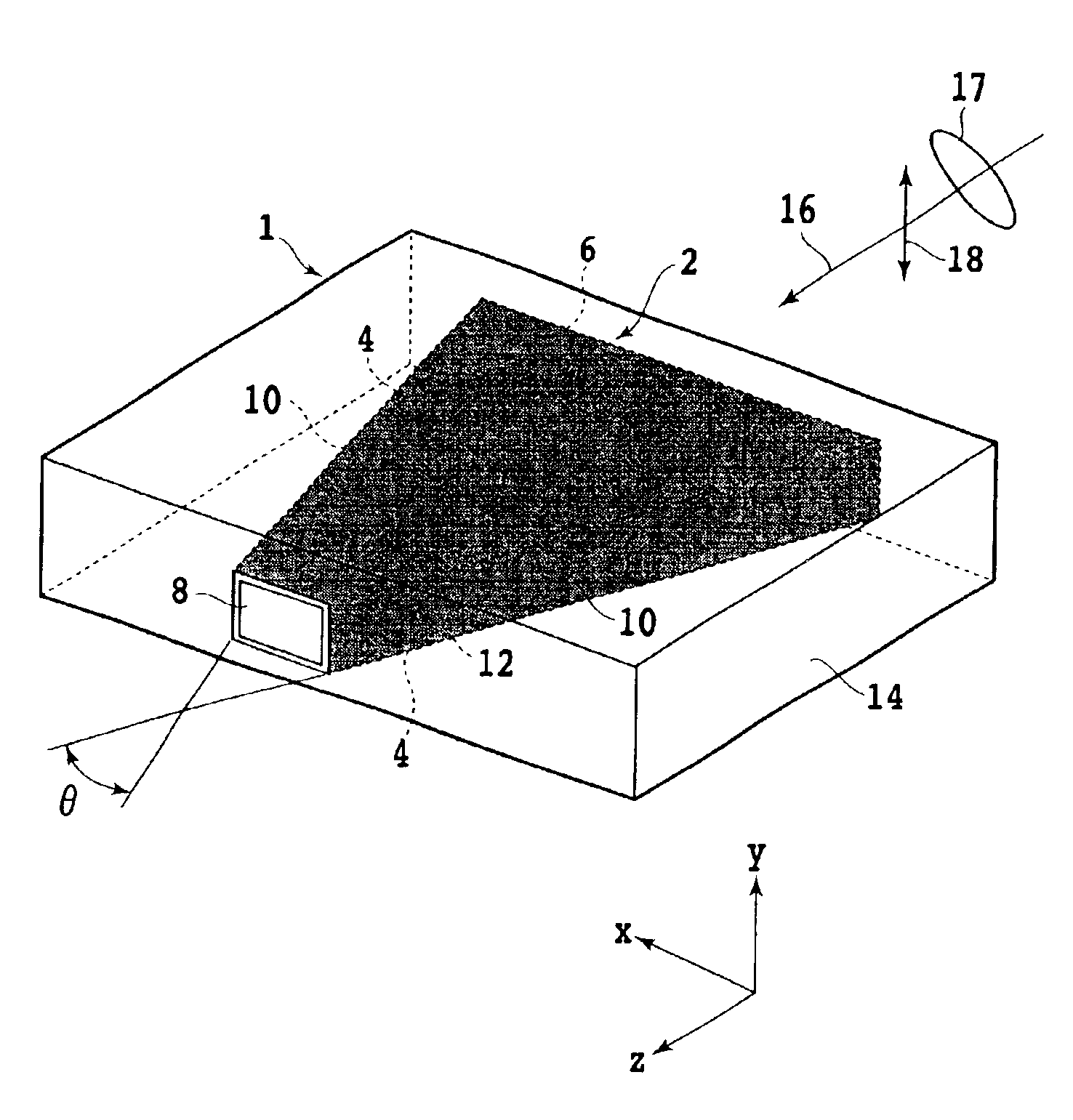
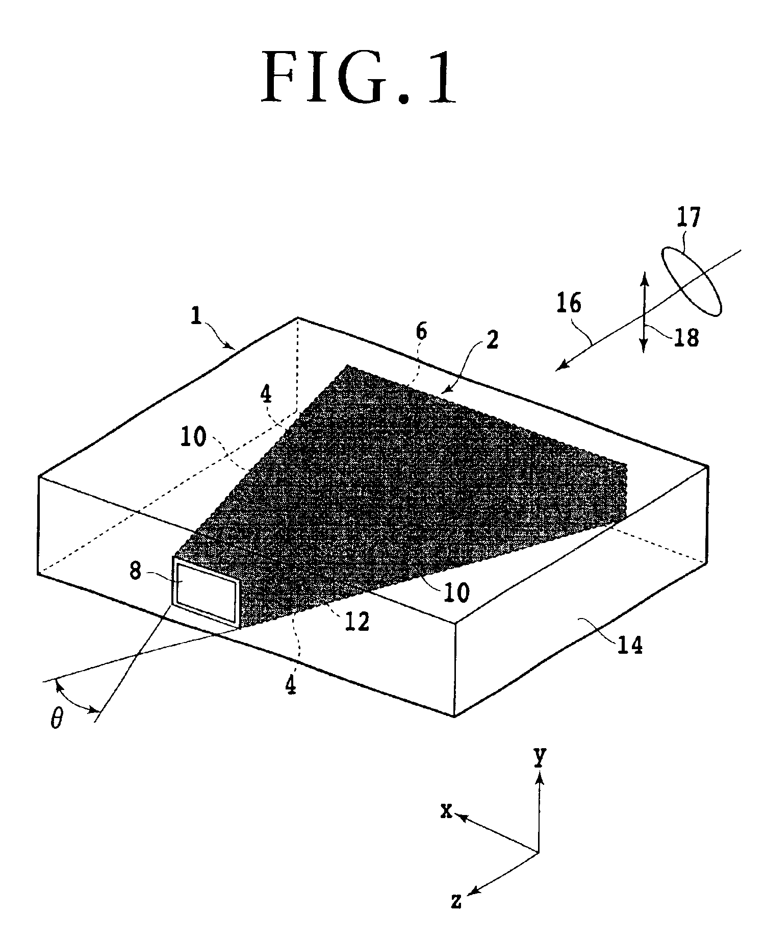
[0035]Referring to FIG. 1, there is shown a schematic perspective view of an optical irradiation head or near-field optical irradiation head according to a first preferred embodiment of the present invention. A trapezoidal prism 2 formed of a dielectric is embedded in a pattern forming substrate 14 such as an Si substrate. The trapezoidal prism 2 has such a shape as obtained by cutting off an apex angular portion of an isosceles triangular prism. That is, the trapezoidal prism 2 has a pair of trapezoidal principal surfaces 4 parallel to each other, a rectangular bottom surface 6, a rectangular top surface 8 parallel to the rectangular bottom surface 6, and a pair of oblique side surfaces 10 connecting the top surface 8, the bottom surface 6, and a pair of principal surfaces 4.

[0036]The trapezoidal prism 2 is covered with a coating 12 such as a metal coating except the bottom surface 6 and the top surface 8. The materials of the trapezoidal prism 2 and the coating 12 are so related a...


PUM


Abstract

An optical irradiation head including a trapezoidal prism having a pair of trapezoidal principal surfaces parallel to each other, a rectangular bottom surface, a rectangular top surface parallel to the rectangular bottom surface, and a pair of oblique side surfaces connecting the top surface, the bottom surface, and the principal surfaces, and a cover member for covering the principal surfaces and the oblique side surfaces. The trapezoidal prism is formed of a first material, and the cover member is formed of a second material. Linearly polarized light having a polarization direction perpendicular to the principal surfaces is incident on the bottom surface. For example, the first material is a dielectric transparent to the incident light, and the second material is metal such as Al, Au, or Ag.

Description

BACKGROUND OF THE INVENTION[0001]1. Field of the Invention[0002]The present invention relates to an optical irradiation head and an information recording / reproducing device using the optical irradiation head.[0003]2. Description of the Related Art[0004]With the progress of information society, the quantity of information is increasing more and more. In response to such an increase in the quantity of information, there is a demand for a very high-density information recording method and a recording / reproducing device based on this method. As a recording method for realization of high-density recording, attention is being given to a near-field optical recording method such that a microscopic aperture smaller than the wavelength of incident light is formed and near-field light generated from this aperture is used to form a beam spot smaller than the wavelength of incident light.[0005]For example, Japanese Patent Laid-open No. Hei 10-206660 discloses an aperture formed at a sharpened en...

Claims


Application Information

Patent Timeline
IPC IPC(8): G11B5/127G11B5/48G11B7/135G11B5/00G11B5/012G11B5/39G11B7/12G11B7/1359G11B7/1387G11B11/105
CPCB82Y10/00G11B5/127G11B5/488G11B7/1359G11B7/1387G11B11/10536G11B11/10554G11B5/012G11B5/3903G11B5/4886G11B2005/0005G11B2005/0021
Inventor TAWA, FUMIHIROHASEGAWA, SHINYA
Owner FUJITSU LTD
Why Eureka
Try Eureka