Remotely deployed optical fiber circulator

a circulator and optical fiber technology, applied in the field of optical fiber signal transmission, can solve the problems of limiting the distance over which optical sensing systems can be employed, limiting the achievable deployment distance, and reducing the range of optical sensing systems. the effect of expanding the distances that optical sensing systems can span

Inactive Publication Date: 2005-08-23
OPTOPLAN
View PDF21 Cites 66 Cited by
  • Summary
  • Abstract
  • Description
  • Claims
  • Application Information

AI Technical Summary

Benefits of technology

[0010]Fiber-optic-based systems and methods for monitoring physical parameters using a remotely deployed circulator are disclosed. In a preferred embodiment the circulator is remotely deployed with respect to an optical source / detector and coupled thereto by two dedicated fiber optical cables: a forward line for passing light from the source through the circulator to fiber-optic-based sensors, and a return line for passing light reflected from the sensors through the circulator back to the detector. By using separate forward and return lines in conjunction with the circulator, backwards-propagating optical scattering noise phenomenon experienced on the forward line will not interfere with the reflected light signals coming from the sensors. The circulator, and hence the sensors, may therefore be remotely deployed from the source / detector present at a monitoring station, greatly expanding distances which optical sensing systems can span. In one embodiment, the circulator is integrated with a wellhead that sits on top of the ocean floor, and allows the wellhead to be deployed at greater distances than were before achievable.

Problems solved by technology

As oil and gas reserves have been increasingly consumed over the years, the extraction of these hydrocarbons has become more difficult.
The resultant development and exploitation of remote oil and gas resources in increasingly difficult operating environments such as deep water have given rise to numerous new technological challenges.
However, the use of fiber optic systems in such environments has resulted in several significant problems that have limited their use to date.
Optical scattering phenomenon, such as Rayleigh backscatter in reflective single-fiber optic sensor transmission line systems, can limit the achievable deployment distances.
Similarly, Mie (scattering of visible light wavelengths by spherical particles), Brillouin (scattering due to the interaction of laser light with sound waves) and Raman (scattering of laser light as it passes through a transparent medium) scattering phenomena further limit the distance over which optical sensing systems can be employed due to the elevated signal-to-noise ratio they cause.
Other optical scattering noise such as Freznel (reverse propagating) reflections due to the connectors or couplers used in optical fiber technology can further contribute to high signal-to-noise ratio.
While there have been numerous patents and publications describing methods for measuring physical parameters using fiber optic systems, few address the issue of backscatter noise and limited monitoring distance.
However, these approaches suffer from several limitations.
First, electronic equipment may be unable to withstand the harsh conditions of a downhole system, and in the event of a failure or breakdown would be very difficult and expensive to retrieve.
Similarly, while placing an amplifier at the wellhead would increase the amplitude of the reflected signal, the associated noise of optical backscattering phenomena would increase as well.

Method used


Image

  • Remotely deployed optical fiber circulator
  • Remotely deployed optical fiber circulator
  • Remotely deployed optical fiber circulator

Examples


Embodiment Construction

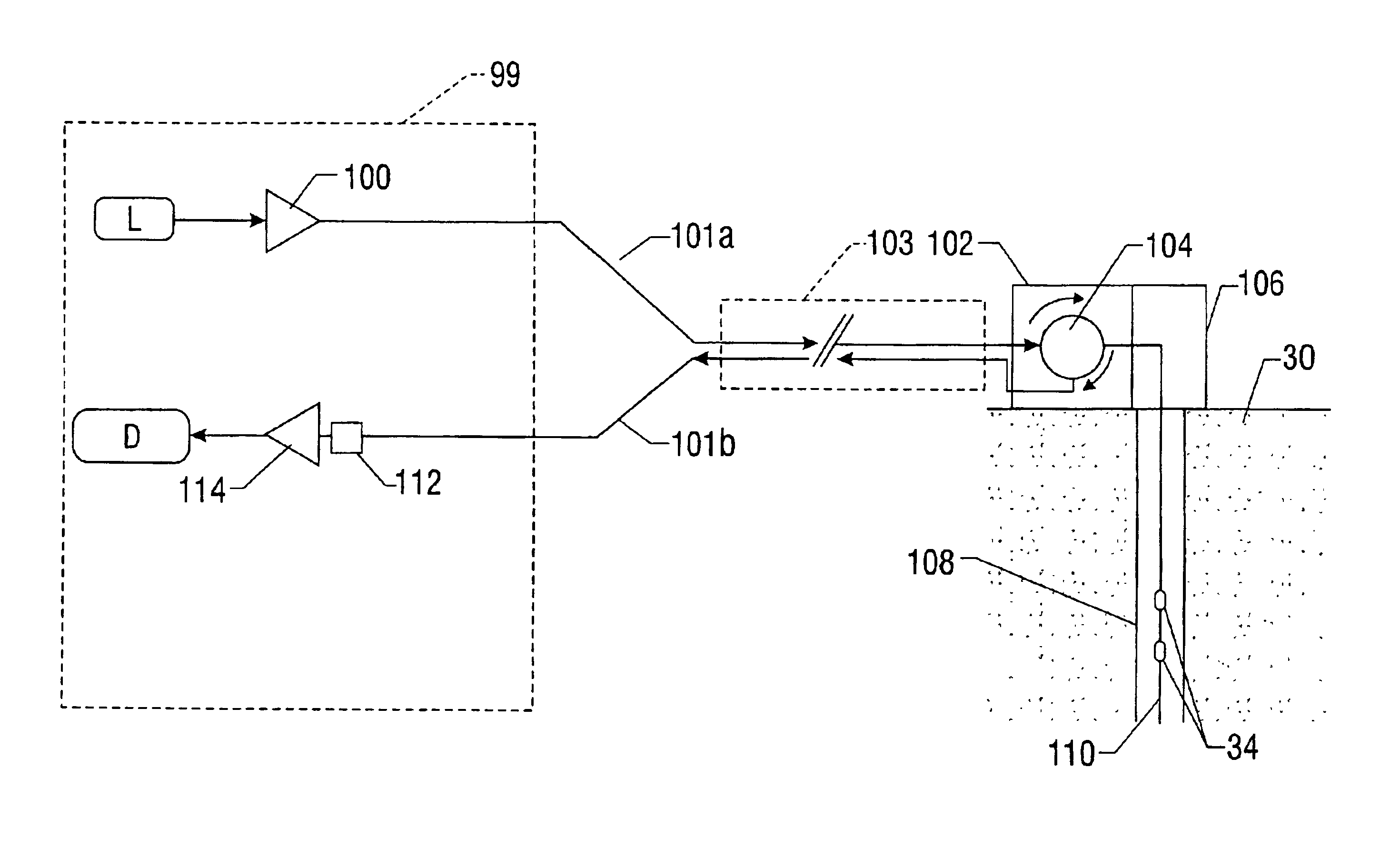
[0021]The present invention relates to a system for monitoring and controlling production wells from a remote location using fiber optic technology. In particular, in an embodiment of the present invention, an optical circulator is remotely located within a wellhead at the top of the oil or gas well, and a separate return fiber is provided from the circulator back to the control system. In this manner, backwards-propagating optical scattering noise is minimized or eliminated, resulting in an improved optical signal-to-noise ratio and improved deployment distance of the fiber optic monitoring system.

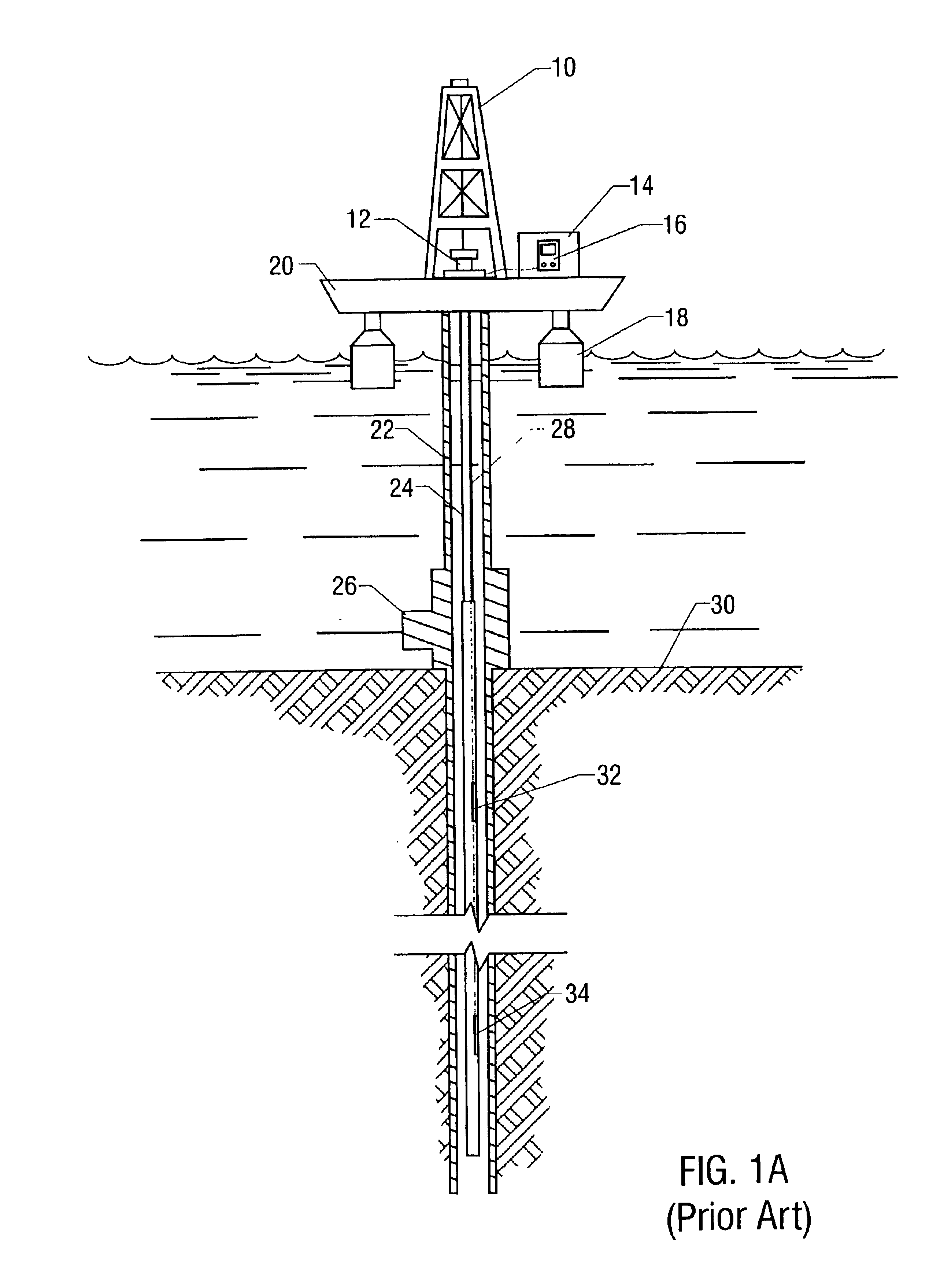
[0022]A typical arrangement for an offshore fiber optic monitoring system according to the prior art is shown in FIG. 1A. Such an arrangement typically includes a floating workstation 18 or similar deep-water production system (e.g. fixed-leg platform, compliant tower, tension-leg platform (TLP), semi-submersible platform, or spar platform system) stationed over a submerged worksite on th...


PUM

PropertyMeasurementUnit
lengthaaaaaaaaaa
distanceaaaaaaaaaa
wavelengthsaaaaaaaaaa

Abstract

Fiber-optic-based systems and methods for monitoring physical parameters using a remotely deployed circulator are disclosed. In a preferred embodiment the circulator is remotely deployed with respect to an optical source / detector and coupled thereto by two dedicated fiber optical cables: a forward line for passing light from the source through the circulator to fiber-optic-based sensors, and a return line for passing light reflected from the sensors through the circulator back to the detector. By using separate forward and return lines in conjunction with the circulator, backscattering phenomenon experienced on the forward line will not interfere with the reflected light signals coming from the sensors. The circulator, and hence the sensors, may therefore be remotely deployed from the source / detector present at a monitoring station, greatly expanding distances which optical sensing systems can span.

Description

BACKGROUND OF THE INVENTION[0001]1. Field of the Invention[0002]The present invention relates generally to the field of optical fiber signal transmission. More particularly, it relates to apparatus and methods for the remote measurement of physical parameters using fiber optic elements including a remote optical circulator in a system of optical fiber cables and optical fiber sensors.[0003]2. Description of Related Art[0004]As oil and gas reserves have been increasingly consumed over the years, the extraction of these hydrocarbons has become more difficult. The resultant development and exploitation of remote oil and gas resources in increasingly difficult operating environments such as deep water have given rise to numerous new technological challenges. Notably, there is an increased need for reserves and wells to be more widely monitored, especially for those hydrocarbon reserves lying deep below the ocean seabed.[0005]Recent developments in fiber optic sensing technology, such as...

Claims


Application Information

Patent Timeline
Patent Type & Authority Patents(United States)
IPC IPC(8): G01N21/77G01N33/28G01N33/26G02B6/26
CPCE21B47/123G01N21/774G01N33/2823G01V11/002H04B10/2503G01N2201/084G02B6/2746E21B47/135H04B10/2589G01D5/268G01N21/7703
Inventor MAIDA, JR., JOHN L.
Owner OPTOPLAN
Why Eureka
Try Eureka