Steam-generating combustion system and method for emission control using oxygen enhancement

a technology of steam-generating combustion and oxygen enhancement, which is applied in the direction of emissions prevention, combustion types, separation processes, etc., can solve the problems of increasing the capital cost of the facility, large devices, and affecting human health, so as to reduce the overall cost of emission control and reduce the mass flow rate of flue gas exiting

Inactive Publication Date: 2005-08-30
AIR LIQUIDE AMERICA INC +1
View PDF19 Cites 56 Cited by
  • Summary
  • Abstract
  • Description
  • Claims
  • Application Information

AI Technical Summary

Benefits of technology

[0013]In accordance with a further embodiment of the present invention a method of steam-generating combustion includes providing an oxygen-enriched gas stream with an oxygen content of 21% to 100%, creating an oxidant stream containing the oxygen enriched gas stream, combusting a fuel in the oxidant stream in a steam-generating combustion chamber and generating flue gas having a flue gas mass flow rate which is smaller than a mass flow rate of flue gas generated by the combustion chamber when operated with the same mass flow rate of fuel and with air as the oxidant stream, and reducing the amount of at least one of particulate matter, SOx, NOx, and mercury in the flue gas with a flue gas pollutant control system.
[0014]In accordance with another embodiment of the present invention a method of retrofitting or repowering a commercial air-fired, steam-generating combustion system to reduce overall cost of emission control includes adding an oxygen-enriched gas generation system to the air-fired, steam-generating combustion system to deliver an oxygen enriched stream with 21% to 100% oxygen, delivering the oxygen-enriched stream to an oxidant delivery system to produce an oxidant stream for a combustion chamber of the combustion system, achieving a reduced mass flow rate of flue gas exiting the combustion chamber due to enhancement of the oxidant with the oxygen-enriched gas stream, and modifying a flue gas pollution control system of the combustion system to take advantage of the flue gas mass flow rate reduction.

Problems solved by technology

All these substances have been proven to be detrimental to human health.
These devices are large and very expensive to purchase and operate, significantly raising the capital cost of the facility and increasing operating costs.
They typically require large amounts of space at the plant site and increase the cost of electricity produced at an electric utility by up to fifty percent.
Thus, the flue gas treatment cost, based on the volume of flue gas to be treated, remains substantially constant when changing from air firing to oxygen enriched firing in glass making furnaces.
Thus, the improved NOx emissions and energy efficiency resulting from oxygen enriched firing in glass furnaces do not always translate to an associated cost savings in these furnaces.
In contrast, in steam generating boilers, such as those used in electric power generating facilities, the amount of pollution produced by the boiler is generally high due to the fuels used and the cost of pollution control is a very significant portion of the cost of producing power.
However, because of the important amount of gas to be treated, the power consumption of the reactor can be fairly high, up to about 5% of the power plant.

Method used


Image

  • Steam-generating combustion system and method for emission control using oxygen enhancement
  • Steam-generating combustion system and method for emission control using oxygen enhancement
  • Steam-generating combustion system and method for emission control using oxygen enhancement

Examples


case 1

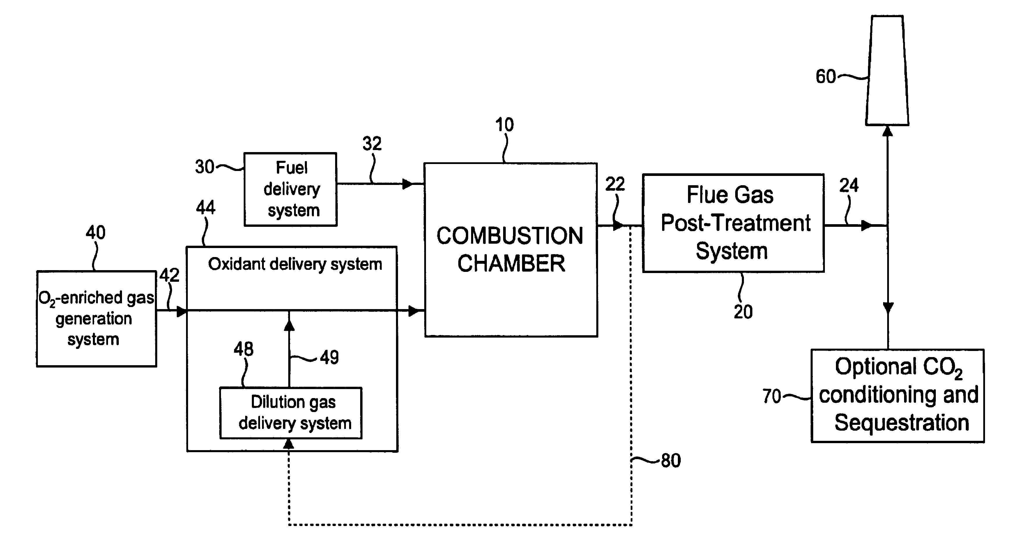
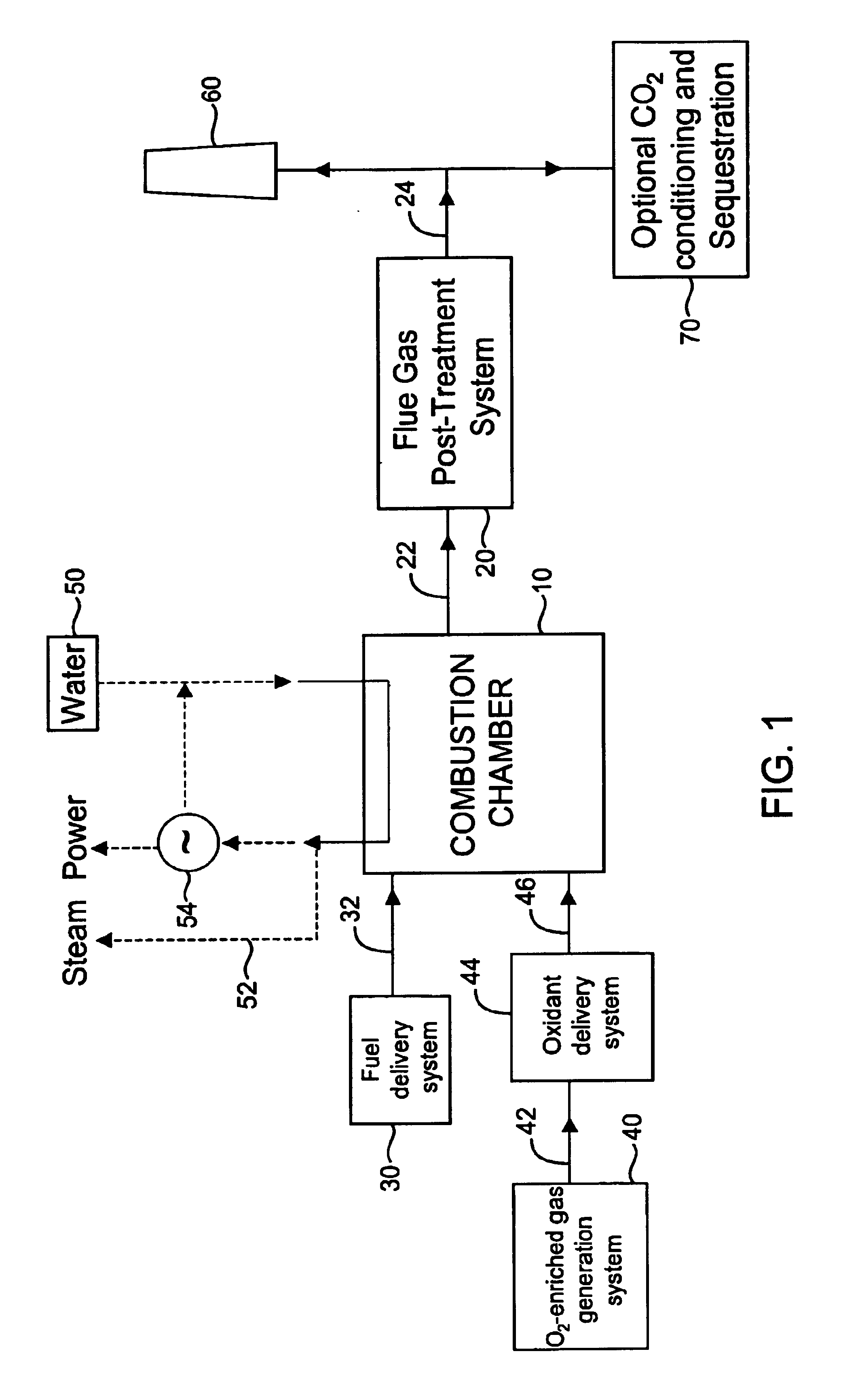
[0064] The boiler is a retrofit O2-blown system with flue gas recirculation (FGR). FGD, SCR, ESP, and Hg systems are used.

case 2

[0065] The boiler is retrofit O2-blown system with flue gas recirculation (FGR). FGD, ESP, and Hg systems are used. No SCR is required due to the NOx reductions resulting from oxy-combustion.

case 3

[0066] The boiler is a new, compact full O2-blown unit without FGR or any other dilution gas. FGD, ESP, and Hg systems are used. No SCR is used due to the NOx reductions resulting from oxy-combustion.

[0067]

TABLE 1 Capital costs ($MM) of air-fired vs. oxygen-firedsystems in three cases.PLANT SIZE (MWe)50020010030OxidantAirO2AirO2AirO2AirO2Post-FGD$129.60$83.80$78.50$55.10$59.50$41.70$36.70$25.80treatmentUnitCostsSCR$30.70$11.40$16.90$6.30$10.80$4.00$4.90$1.80Hg$0.75$0.21$0.36$0.10$0.21$0.06$0.08$0.02(carboninjection)ESP$25.00$8.90$13.60$4.80$8.60$3.10$3.90$1.40Total Post-$186.05$104.31$109.36$66.30$79.11$48.86$45.58$29.02treatment costPost-treatment cost−44%−39%−38%−36%vs base caseoxygen-enriched gas$89.80$35.90$22.10$9.50generation cost(ASU)Case 1Steam generating combustion$210.00$210.00$84.00$84.00$42.00$42.00$12.60$12.60system (Boiler)Plant capital cost$396.05$404.11$193.36$186.20$121.11$112.96$58.18$51.12Plant capital cost vs2%−4%−7%−12%base caseCase 2steam generating combu...


PUM

PropertyMeasurementUnit
mass flow rateaaaaaaaaaa
purityaaaaaaaaaa
water solubleaaaaaaaaaa

Abstract

A steam-generating combustion system includes an oxygen enriched gas provided as at least part of an oxidant stream. A combustion chamber receives and combusts a fuel in the oxidant stream and generate steam. The combustion chamber generates flue gas having a flue gas volume which is smaller than a volume of flue gas generated by the combustion chamber when operated with air as the oxidant stream. A flue gas pollutant control system receives the flue gas from the combustion chamber and reduces at least one of particulate matter, SOx, NOx, and mercury. The reduction in flue gas volume allows the implementation of much smaller pollutant control equipment, since the size of the pollutant control units is mainly based on the volume or mass flow rate of flue gas to be treated. Moreover, the system including oxygen-enriched gas in the oxidant will lead to concentrated levels of the pollutants in the flue gas. The high concentrations of pollutants will enhance their absorption in the different pollutant control systems, improving removal efficiency for all species.

Description

CROSS REFERENCE TO RELATED APPLICATIONS[0001]This application claims priority to U.S. Provisional Patent Application No. 60 / 357,414, filed Feb. 15, 2002, and U.S. Provisional Patent Application No. 60 / 380,808, filed May 15, 2002, which are incorporated herein by reference in their entirety.FIELD OF THE INVENTION[0002]The invention relates to a system and method for improved emissions control from a steam-generating combustion system using a combination of an oxygen-enhanced firing process and flue gas treatment systems.DESCRIPTION OF THE RELATED ART[0003]Industrial combustion systems are the main source of sulfur dioxide (SO2), nitrogen oxides (NOx) and mercury (Hg) emissions, as well as carbon dioxide (CO2). Whether it is through the Kyoto Protocol or through recent initiatives from the U.S. government, these industrial combustion plants will now have to comply with more and more stringent regulations regarding these pollutants.[0004]The combustion of fossil fuels in utility boiler...

Claims


Application Information

Patent Timeline
Patent Type & Authority Patents(United States)
IPC IPC(8): B01D53/32F23J15/00F23L7/00F23G5/50F23G7/06F23M3/00
CPCB01D53/32F23G5/50F23G7/061F23J15/006F23L7/005F23L7/007F23G2204/201F23J2215/10F23J2215/20F23J2215/50F23J2215/60F23J2217/102F23J2900/15061F23L2900/07001F23L2900/07007Y02E20/12Y02E20/322Y02E20/344Y02E20/32Y02E20/34
Inventor MARIN, OVIDIUMACADAM, SCOTTPENFORNIS, ERWINCHATEL-PELAGE, FABIENNE
Owner AIR LIQUIDE AMERICA INC
Why Eureka
Try Eureka