Magnetic sensor with pointing control circuit

a pointing control circuit and sensor technology, applied in the field of magnetic sensors, can solve the problems of difficult to obtain sufficient magnetic sensitivity, silicon hall elements not being widely used, etc., and achieve the effect of excellent performance and reducing the area exclusively occupied by the pointing control circui

Inactive Publication Date: 2005-08-30
ROHM CO LTD
View PDF1 Cites 17 Cited by
  • Summary
  • Abstract
  • Description
  • Claims
  • Application Information

AI Technical Summary

Benefits of technology

[0017]The invention has an advantageous effect in that an area exclusively occupied by the pointing control circuit can be reduced since the Hall elements are disposed in the four corners of a chip, which is a dead space thereof, respectively, and the Hall elements are formed integrally with the pointing control circuit on the chip. Further, as a result of disposing the Hall elements in the four corners of the chip, respectively, both the Hall elements and chip are insusceptible to the effect of noises, thus rendering the invention advantageous from the viewpoint of noises as well.
[0018]Furthermore, since the Hall elements and the pointing control circuit are united together to be thereby formed on one chip, fluctuation in respective characteristics of the Hall elements, differential amplifiers, pointing control circuit, and so forth can be adjusted on the basis of the chip as a whole, so that fluctuation in the characteristic of a system in whole is eliminated, thereby enabling a magnetic sensor excellent in performance to be constructed.
[0019]In addition, by uniting the Hall elements with the pointing control circuit, it becomes possible to implement a device easy to handle as a magnetic sensor in the form of a single device.

Problems solved by technology

Further, with the conventional pointing device, gallium arsenide (GaAs), indium antimonide (InSb), and so forth have been used as material for the Hall elements as constituent members of the magnetic sensor, however, Hall elements using silicon have not been in widespread use.
This is because in the case of implementing integration of the Hall elements using silicon, it is difficult to obtain sufficient magnetic sensitivity in comparison with the case of using the material as described above.

Method used


Image

  • Magnetic sensor with pointing control circuit
  • Magnetic sensor with pointing control circuit
  • Magnetic sensor with pointing control circuit

Examples


first embodiment

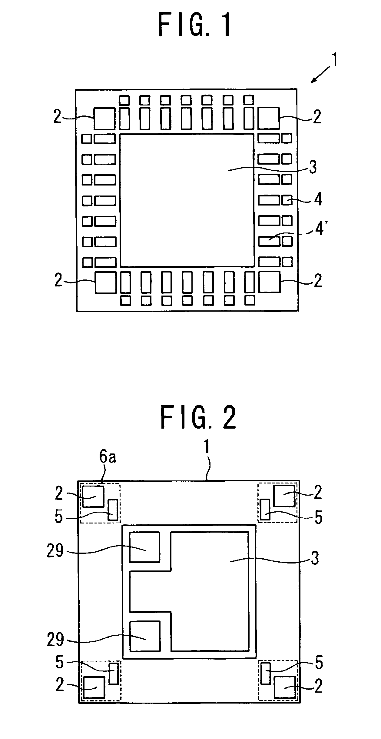
[0036]FIG. 1 is a plan view of a magnetic sensor with a pointing control circuit according to the invention. The magnetic sensor 1 with the pointing control circuit comprises an IC chip, substantially square in shape, with the pointing control circuit 3 formed in the central part thereof, and bonding pads 4 for the pointing control circuit 3, and input / output (I / O) parts 4′, disposed on the peripheral region of the pointing control circuit 3. The bonding pads 4 are connected with lead electrodes of a lead frame with a thin gold wire, respectively, and Hall elements 2 are disposed on four corner parts of the IC chip, respectively.

[0037]Two pairs of the Hall elements 2 disposed diagonally opposite to each other, on the IC chip square in shape, respectively, correspond to the pairs of the Hall elements disposed along the x-axis or the y-axis of the conventional magnetic sensor shown in FIG. 15, respectively, and a circuit condition is set such that the respective Hall elements 2 delive...

third embodiment

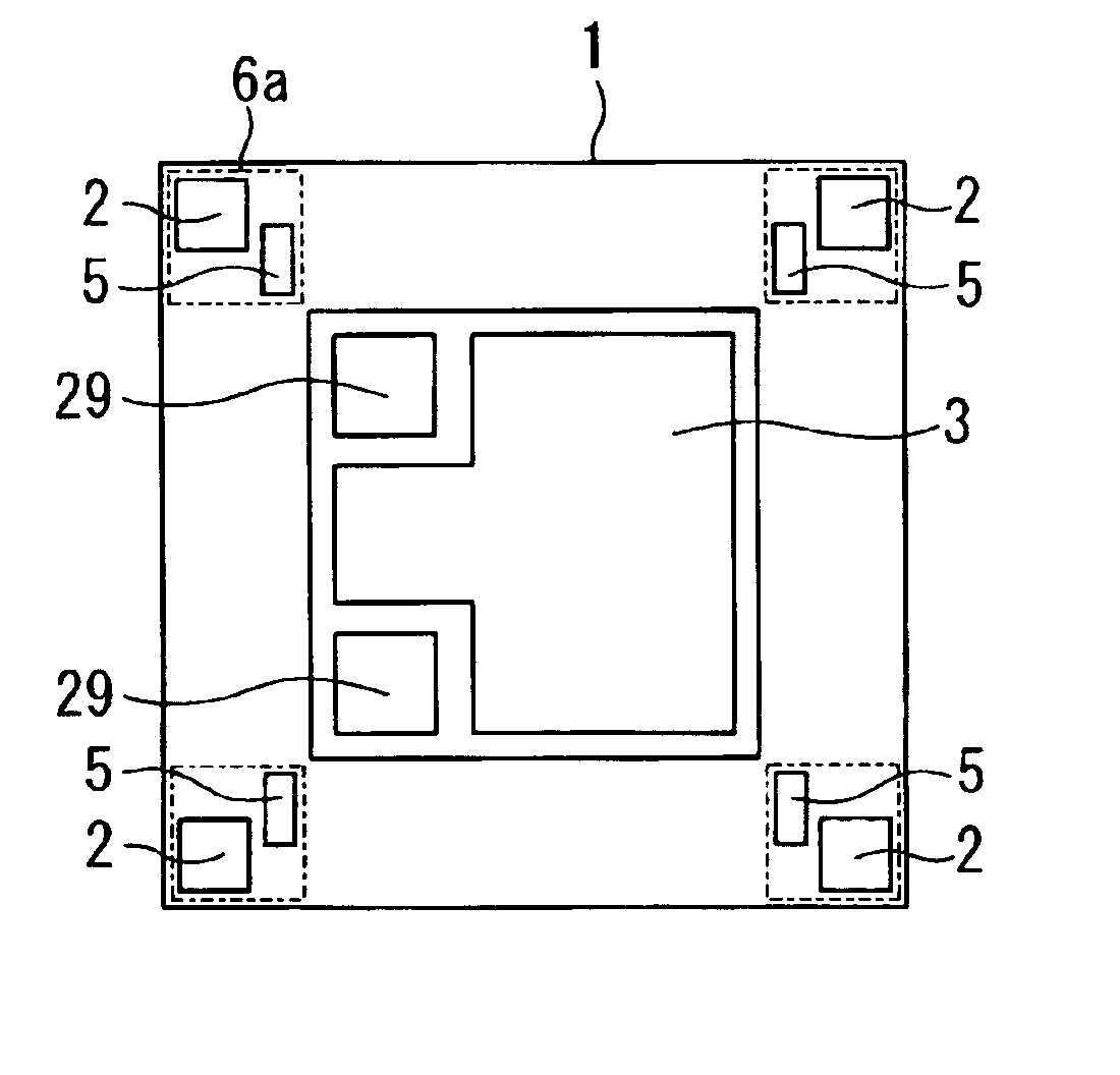
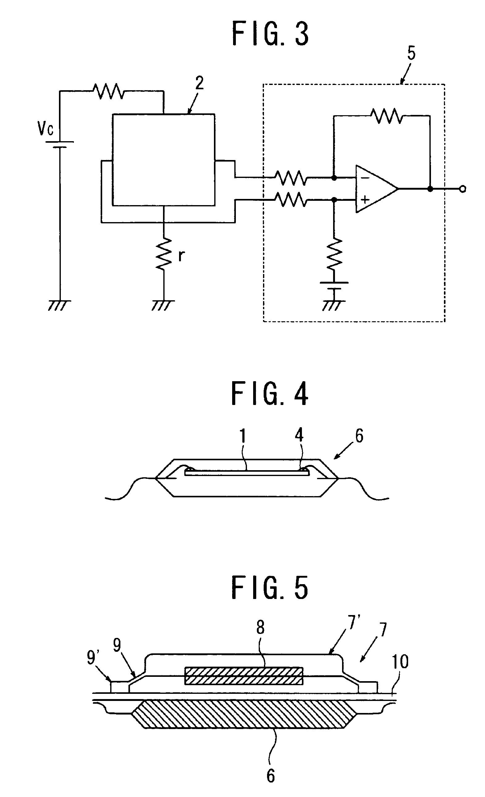
[0041]FIG. 2 is a plan view of a magnetic sensor with a pointing control circuit according to the invention. In order to employ Hall elements made of material low in magnetic sensitivity for use in a magnetic sensor, outputs of the Hall elements need to be amplified. FIG. 3 shows an amplifier circuit used for such a purpose. For the amplifier circuit, a differential amplification circuit (hereinafter referred to as a pre-amp) 5 is used, and the pre-amp 5 is formed in close proximity to a Hall element 2, and formed integrally therewith in four corner parts of the IC chip in the process of integrating the pointing control circuit 3. In this case, the pre-amp 5 can be formed so as to be adjacent to the Hall element 2, as shown in FIG. 2, or may be formed so as to be disposed above or below in relation to the Hall element 2 shown in FIG. 2.

[0042]With the present embodiment, the Hall elements 2, the pre-amps 5, and the pointing control circuit 3 are integrated by uniting those components...


PUM

PropertyMeasurementUnit
output voltageaaaaaaaaaa
magnetic sensitivityaaaaaaaaaa
magnetic fieldaaaaaaaaaa

Abstract

A configuration comprising a magnetic sensor and a pointing control circuit, for implementing a pointing device, is rendered compact in size.
To that end, the pointing control circuit is formed in the central part of an IC chip, substantially square in shape, and Hall elements are provided in four corners of the peripheral region of the pointing control circuit, respectively, thereby forming the magnetic sensor, comprising the Hall elements, integrally with the pointing control circuit. Further, the Hall elements are formed integrally with the pointing control circuit in the step of fabricating an IC, thereby uniting the Hall elements with the pointing control circuit.

Description

FIELD OF THE INVENTION[0001]The present invention relates to a magnetic sensor of a pointing device, for use as input means of information equipment, such as a personal computer, cellular phone, and so forth, and in particular, to a magnetic sensor with a pointing control circuit, for detecting coordinates by detecting a change in a magnetic field due to movement of a magnet, and information equipment using the same.BACKGROUND OF THE INVENTION[0002]A pointing device such as a joy stick, track ball, and so forth, has since been in use as input means for a personal computer, cellular phone, and so forth. As a sensor of the pointing device, an optical sensor, a pressure sensitive sensor, variable resistance sensor, and magnetic detection sensor have been put to commercial use, however, among those, the magnetic detection sensor small in size, having a long service life, has lately become a favorite one in the market. In particular, a sensor with Hall elements assembled therein has sinc...

Claims


Application Information

Patent Timeline
Patent Type & Authority Patents(United States)
IPC IPC(8): G06F3/033G01R33/02G01P3/42G01R33/07G06F3/0346H01H25/04H01H36/00H01L27/22H01L43/04H01L43/06
CPCG06F3/0338Y10T29/49002G01P3/42
Inventor SAITO, KOICHI
Owner ROHM CO LTD
Why Eureka
Try Eureka