Method and apparatus of sealing wafer backside for full-face electrochemical plating

a technology of electrochemical plating and backside sealing, which is applied in the direction of sealing devices, manufacturing tools, lapping machines, etc., can solve the problems of contaminating the backside and electrical contacts of the wafer, increasing manufacturing costs, and time-consuming, so as to reduce the irregularities of polishing and efficiently configure the wafer carrier head

Inactive Publication Date: 2005-09-06
NOVELLUS SYSTEMS
View PDF22 Cites 34 Cited by
  • Summary
  • Abstract
  • Description
  • Claims
  • Application Information

AI Technical Summary

Benefits of technology

[0014]It is another object of the present invention to provide a wafer carrier that prevents processing liquids and contaminants resulting therefrom from reaching a backside inner region of the wafer.
[0015]It is a further object of the present invention to provide a wafer carrier that prevents processing liquids and contaminants resulting therefrom from reaching an inner region of the base and a backside inner region of the wafer.
[0016]It is a further object of the invention to minimize irregularities in polishing that are caused by using a vacuum to attach a backside of a wafer to a wafer carrier.
[0017]It is a further object of the invention to provide a method to efficiently configure a wafer carrier head to obtain a desired vacuum opening arrangement.
[0019]Further, a sealing member, which is alternatively an o-ring, gasket, or inflatable member is used in combination with the vacuum holes positioned as described above to assist in preventing the processing liquids and contaminants resulting therefrom from reaching the backside inner region of the wafer as well as minimize irregularities in polishing that are caused by using a vacuum to attach a backside of a wafer to a wafer carrier.

Problems solved by technology

Such leakages to the backside of the wafer contaminate the wafer backside and the electrical contacts.
Removal of contaminants from the wafer backside requires an extra process step that is time consuming and increases manufacturing costs.

Method used


Image

  • Method and apparatus of sealing wafer backside for full-face electrochemical plating
  • Method and apparatus of sealing wafer backside for full-face electrochemical plating
  • Method and apparatus of sealing wafer backside for full-face electrochemical plating

Examples


Embodiment Construction

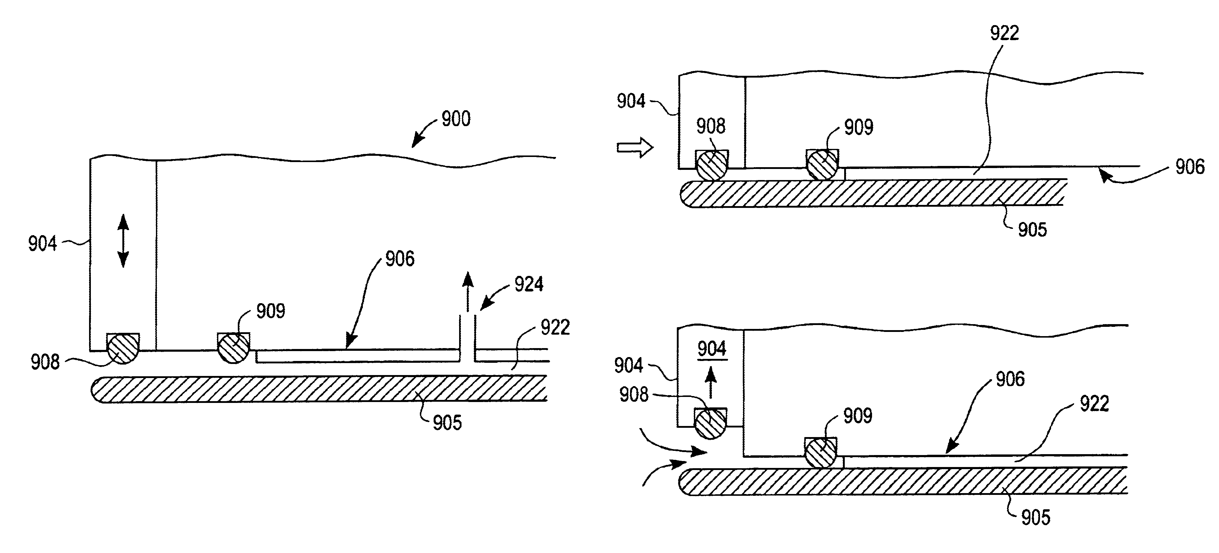
[0035]Reference will now be made to the drawings wherein like numerals refer to like parts throughout. FIG. 2 shows an exemplary processing system 100. When used for electrodeposition, the system 100 may, for example, include a cathode assembly 102 and an anode assembly 104 and can then deposit a conductive material such as copper on a workpiece or substrate, such as semiconductor wafer. When used for material removal, the system 100 may, for example, have the polarity of the anode and cathode reversed, or instead use other processing chemicals. Further, the wafer carrier described herein can be used in a CMP process with CMP solutions, such as a CMP slurry. It should be understood that the particular process in which the present invention is used is not of particular importance. What is significant, as illustrated hereinafter, is prevention of contamination of a processing solution from reaching a backside of a wafer. And in certain embodiments, also allowing for full face processi...


PUM

PropertyMeasurementUnit
diameteraaaaaaaaaa
sizesaaaaaaaaaa
sizesaaaaaaaaaa

Abstract

The present invention provides a wafer carrier that includes a plurality of concentric sealing members that provide a seal, with the outer seal independently movable to allow cleaning of a peripheral backside of the wafer to occur while the wafer is still attached to the wafer carrier, and a plurality of vacuum openings that a re disposed only adjacent to an inner side of the inner seal at a location corresponding to the backside periphery of the wafer.

Description

[0001]This application is a continuation-in-part of and claims priority from U.S. Utility application Ser. No. 09 / 910,686 filed Jul. 20, 2001 now U.S. Pat. No. 6,855,037 and to U.S. Provisional Application No. 60 / 275,406 filed on Mar. 12, 2001 and entitled Wafer Carrier For Wet Processes.BACKGROUND OF THE INVENTION[0002]1. Field of the Invention[0003]The present invention generally relates to semiconductor processing technologies and, more particularly, to a versatile wafer carrier.[0004]2. Description of the Related Art[0005]Conventional semiconductor devices generally include a semiconductor substrate, usually a silicon substrate, and a plurality of sequentially formed dielectric interlayers such as silicon dioxide and conductive paths or interconnects made of conductive materials. The interconnects are usually formed by filling a conductive material in trenches etched into the dielectric interlayers. In an integrated circuit, multiple levels of interconnect networks laterally ext...

Claims


Application Information

Patent Timeline
Patent Type & Authority Patents(United States)
IPC IPC(8): B24B37/04C25D7/12C25D17/06H01L21/67H01L21/683H01L21/00B24B37/30C25D17/00H01L21/304H01L21/306
CPCB24B37/30C25D17/06H01L21/67126C25D17/004H01L21/6838C25D7/123C25D17/001H01L21/6704H01L21/6715H01L21/00H01L21/68
Inventor ASHJAEE, JALALTALIEH, HOMAYOUNBASOL, BULENT M.VOLODARSKY, KONSTANTIN
Owner NOVELLUS SYSTEMS
Why Eureka
Try Eureka