Implantable continuous intraocular pressure sensor

a continuous, intraocular pressure sensor technology, applied in the field of pressure sensors, can solve the problems of intraocular pressure, decreased accuracy of non-contact tonometers, optic nerves, etc., and achieve the effect of wearing safely, comfortably and conveniently

Inactive Publication Date: 2005-09-06
IOSENSOR
View PDF17 Cites 392 Cited by
  • Summary
  • Abstract
  • Description
  • Claims
  • Application Information

AI Technical Summary

Benefits of technology

[0028]A pressure sensor may be incorporated into a pressure measurement system. A pressure measurement system includes a pressure sensor, an external detector pick-up coil disposed proximate the sensor. The system further includes an electronic interface module coupled to the external detector pick-up coil, and a data analysis computer coupled to the electronic interface module. The external detector pick-up coil is a flat, wo

Problems solved by technology

Glaucoma is a potentially blinding disease, distinguished by elevated intraocular pressure (IOP), which if left untreated can lead to optic nerve damage resulting in blindness.
The accuracy of the non-contact tonometer is diminished with higher intraocular pressures and in eyes with abnormal corneas or poor fixation.
The unequivocal need to have a highly trained professional available during intraocular measurements, in addition to the risk of corneal abrasion, reactions to topical anesthetics, and transmission of infectious agents limit the accessibility and ease of monitoring intraocular pressure in glaucoma patients.
Abnormal pressure peaks may occur at odd hours, e.g. very early in the morning, or at times when it is inconvenient to see the patient in the doctor's office and impractical to record the intraocular pressures.
The major disadvantages of these latter procedures are their cost, the drastic modification introduced of the patient's normal activities, and possible introduction of exogenous factors that affect the diurnal pressure, such as in changing the normal sleep pattern, and hence possibly falsely varying the measured intraocular pressures.
Another major disadvantage is the gradual reduction of the intraocular pressure induced by multiple manipulations and pressure applications on the corneal surface, which result in an iatrogenic reduction i

Method used


Image

  • Implantable continuous intraocular pressure sensor
  • Implantable continuous intraocular pressure sensor
  • Implantable continuous intraocular pressure sensor

Examples


first embodiment

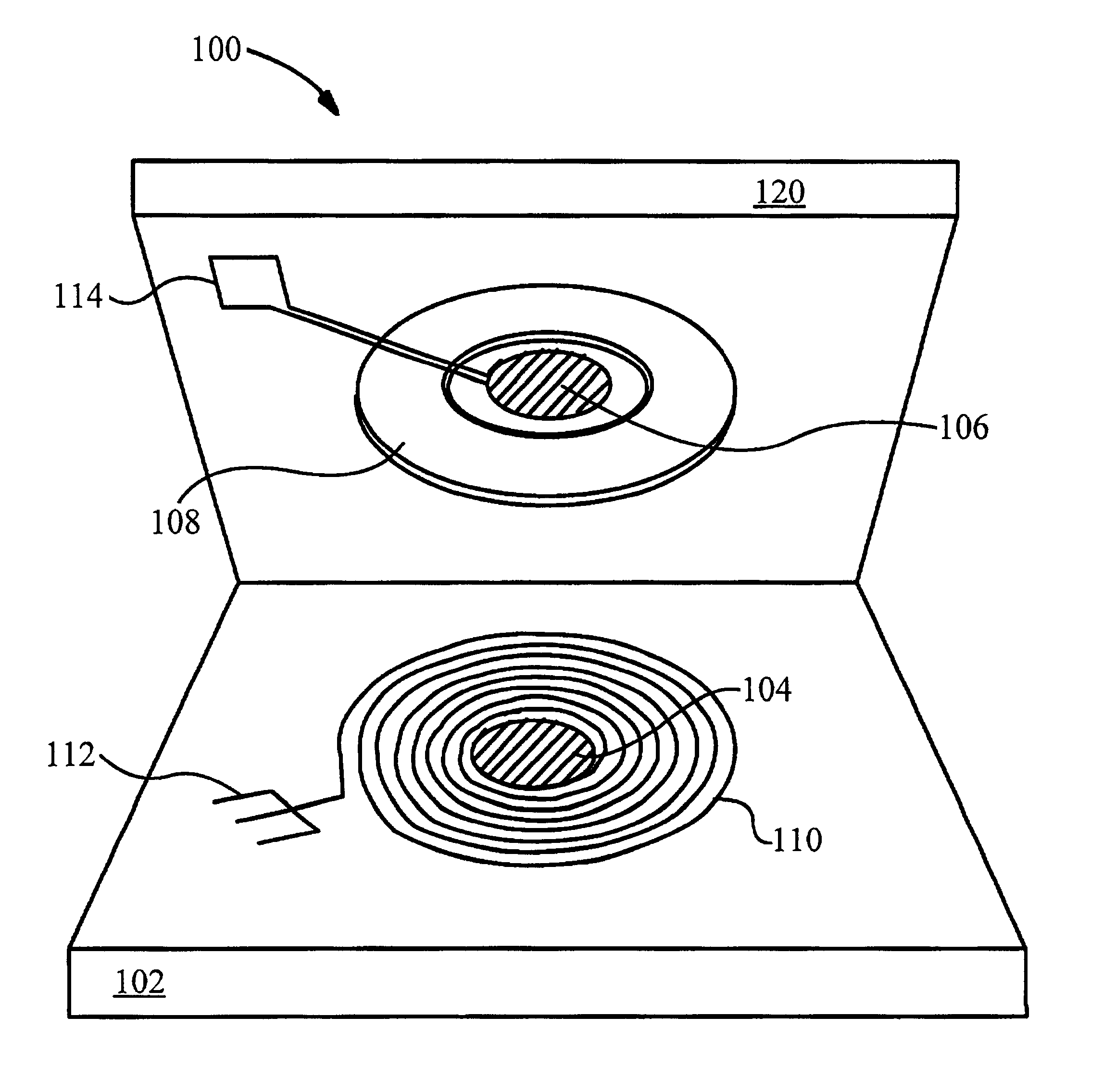
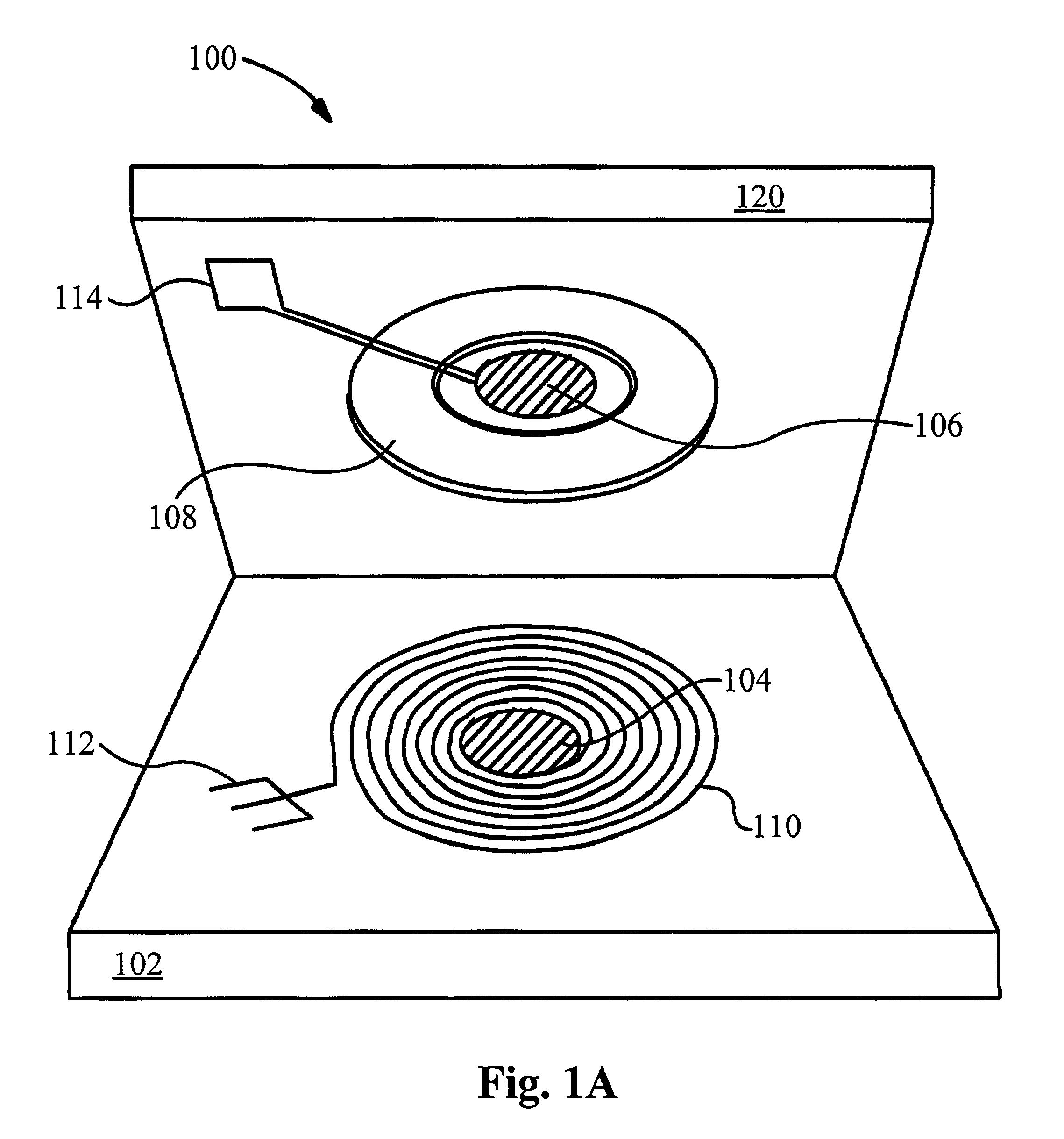
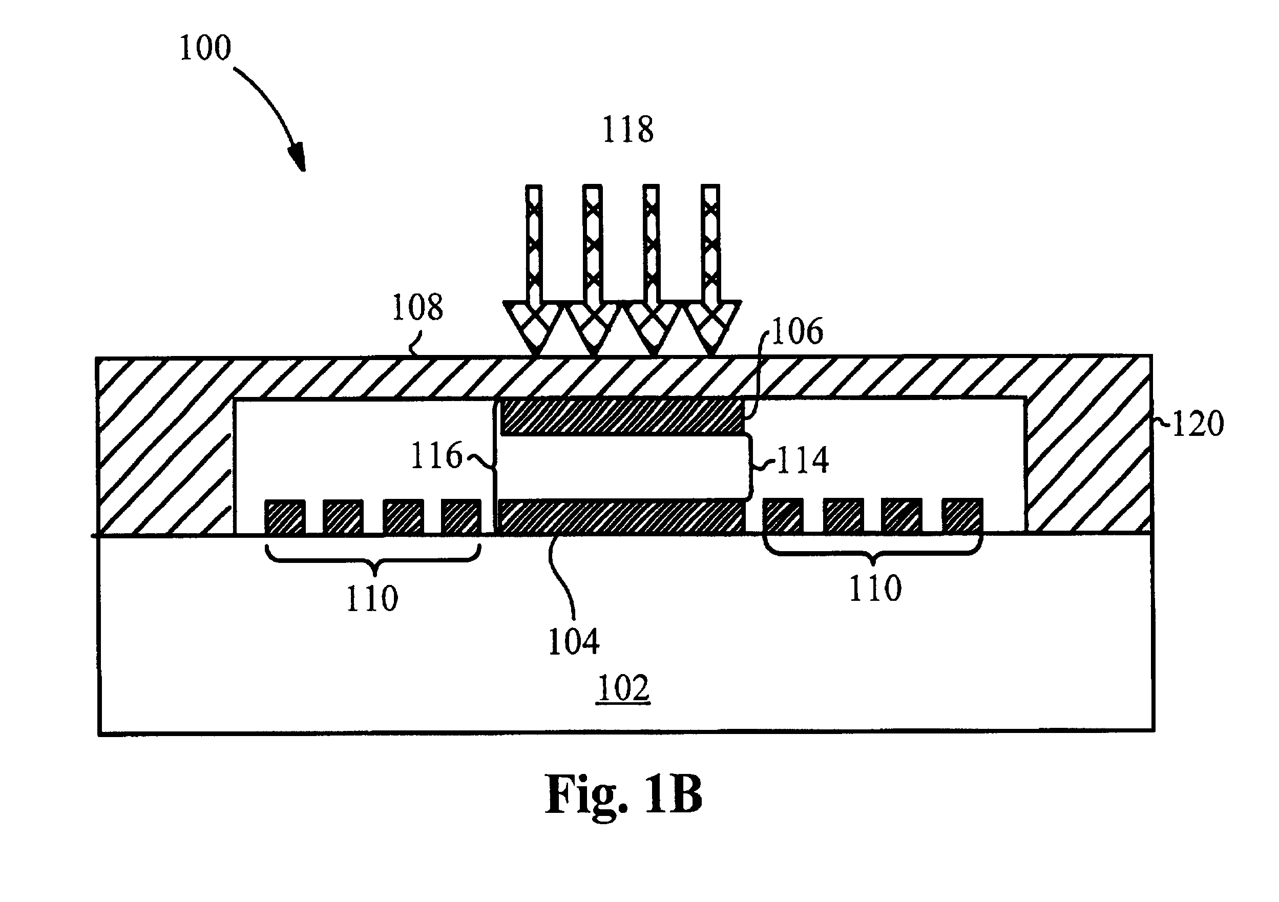
[0044]FIG. 1A shows a split-level view of a pressure sensor 100 according to the present invention. Pressure sensor 100 comprises a lower capacitor plate 104, an upper capacitor plate 106, and an inductor 110. The inductor 110 is a micromachined flat spiral coil that spirals around the lower capacitor plate 104. Typically, the inductor 110 is coplanar with the lower capacitor plate 104, however this need not be the case. The upper capacitor plate 106, the lower capacitor plate 104, and the inductor 110 are typically made of Al, Au or Cu. The lower capacitor plate 104 and the flat inductor coil 110 are placed on top of a substrate 102, which may be a deformable or non-deformable membrane. The substrate 102 is typically made of glass.

[0045]The pressure sensor 100 further includes a deformable membrane 108 bonded to the substrate 120. The membrane 108 is typically made silicon or of plastic materials including Silastic™, amorphous fluoropolymers such as Teflon™ AF, and polyimide such a...

second embodiment

[0046]The pressure sensor 100 illustrated in FIG. 1A may be produced using the flex circuit technology according to the present invention. An exemplary embodiment of the process of fabricating a sensor such as the sensor 100 is shown in FIGS. 2A-2E. As shown in FIG. 2A, polymer film 206 including plastic materials as described above is spun. cast onto a 4-inch silicon wafer 202 coated with a thick release layer of aluminum 204. The silicon wafer 202 allows constructing polymer films 206 from about 5 μm to about 100 μm thick. A thin metal seed layer 208 of Cu or Au is sputtering deposited onto the polymer film 206. A photoresist layer 210 about 25-50 microns thick is spun cast onto the seed layer 208 and patterned to form the coil 110 and capacitor plates 104 and 106, as shown in FIG. 2B. The wafers 200 are placed into an Au plating path and Au is selectively plated up through the openings in the resist 210. The thin metal seed layer 208 is etched away from the areas between the plat...


PUM


Abstract

An implantable miniaturized pressure sensor integrates a capacitor and an inductor in one small chip, forming a resonant LC circuit having a Q value of 10 or greater. The capacitor has an upper capacitor plate and a lower capacitor plate disposed proximate thereof. The upper and lower capacitor plates are connected to one or more spiral inductor coils. The sensor is micromachined from silicon to form a thin and robust membrane disposed on top of the upper capacitor plate. The sensor is hermetically sealed and the membrane is deflected relative to the upper capacitor plate by an external fluid, gas, or mechanical pressure. The resonant frequency of the sensor can be remotely monitored and continuously measured with an external detector pick up coil disposed proximate the sensor. The sensor can be smaller than 2×2×0.5 mm and is particularly useful for intraocular applications.

Description

CROSS-REFERENCE TO RELATED APPLICATIONS[0001]This application is based on Provisional application 60 / 170,450 filed Dec. 13, 1999 which is herein incorporated by reference.FIELD OF THE INVENTION[0002]This invention relates generally to pressure sensors. More particularly, it relates to a remotely monitored implantable continuous intraocular pressure sensor(s).BACKGROUND ART[0003]Glaucoma is a potentially blinding disease, distinguished by elevated intraocular pressure (IOP), which if left untreated can lead to optic nerve damage resulting in blindness. Today's glaucoma therapy consists of mainly monitoring, and lowering the intraocular pressure by medical or surgical therapy.[0004]Measurement of intraocular pressure in glaucoma patients is usually performed in a doctor's office, using one of the presently available external tonometers. Clinical measurement of intraocular pressure is performed by deforming the globe of the eye and correlating the force responsible for the deformation ...

Claims


Application Information

Patent Timeline
IPC IPC(8): A61B3/16
CPCA61B3/16A61B2560/0219A61B2562/0247
Inventor PETERSEN, KURTKOVACS, GREGORY T. A.RYAN, TERENCE G.PARTAMIAN, LEON G.LEE, DAVID A.
Owner IOSENSOR
Why Eureka
Try Eureka