White light emitting phosphor blends for LED devices

Inactive Publication Date: 2005-09-06
GE LIGHTING SOLUTIONS LLC
View PDF18 Cites 142 Cited by
  • Summary
  • Abstract
  • Description
  • Claims
  • Application Information

AI Technical Summary

Problems solved by technology

However, the increased phosphor thickness decreases the system efficiency.
Another disadvantage of the blue LED—YAG:Ce phosphor system is that the LED color output (e.g., spectral power distribution and peak emission wavelength) varies with the band gap width of the LED active layer and with the power applied to the LED.
Furthermore, even if the band gap of a particular LED has the desired width, during LED operation the power applied to the LED frequently deviates from the desired value.
This also causes the LED color output to deviate from the desired parameters.
A significant deviation from the desired parameters may cause the color output of the system to appear non-white (i.e., bluish or yellowish).
Furthermore, the color output of the blue LED—YAG:Ce phosphor system varies greatly due to fre

Method used


Image

  • White light emitting phosphor blends for LED devices
  • White light emitting phosphor blends for LED devices
  • White light emitting phosphor blends for LED devices

Examples


example 1

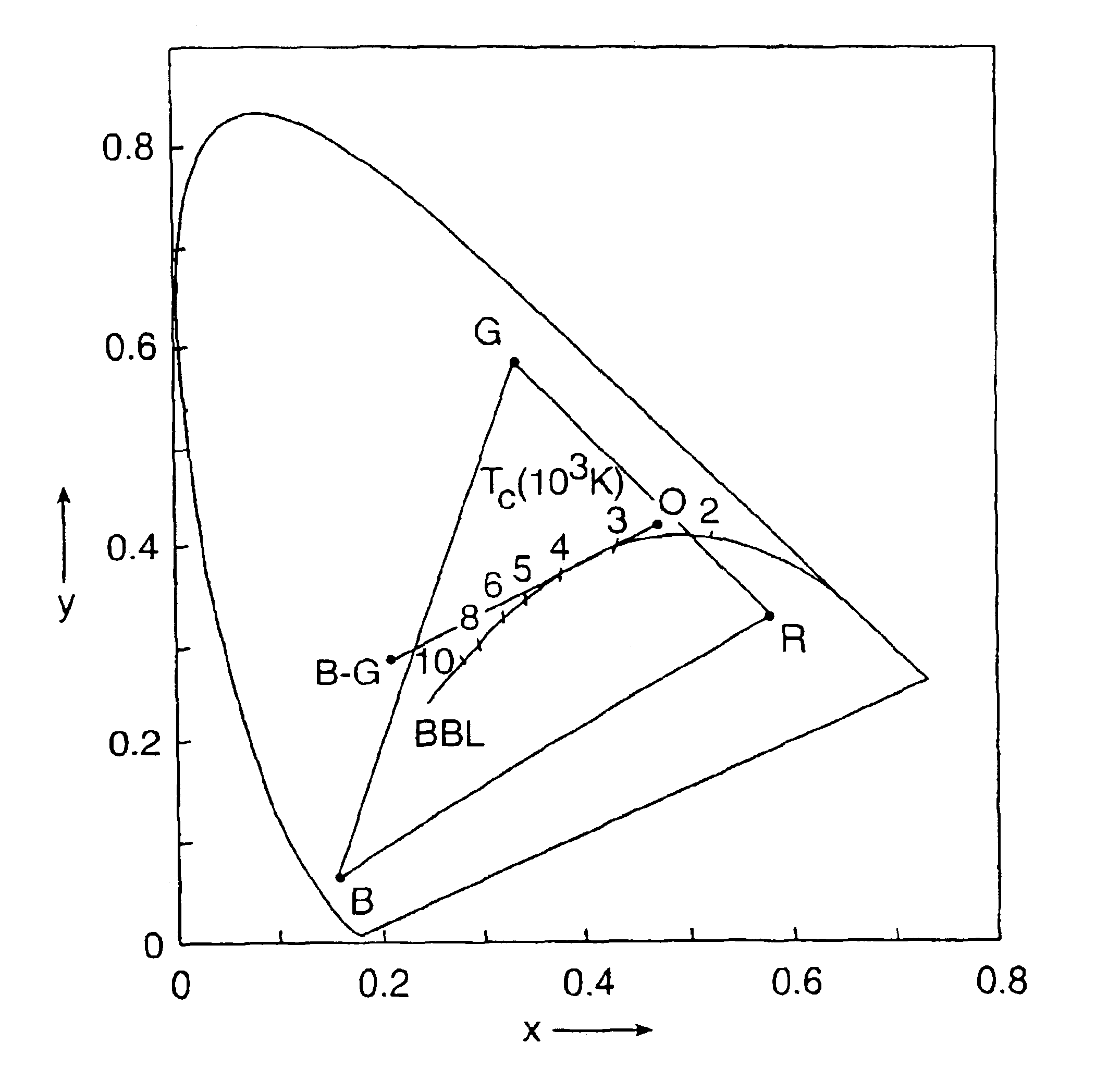
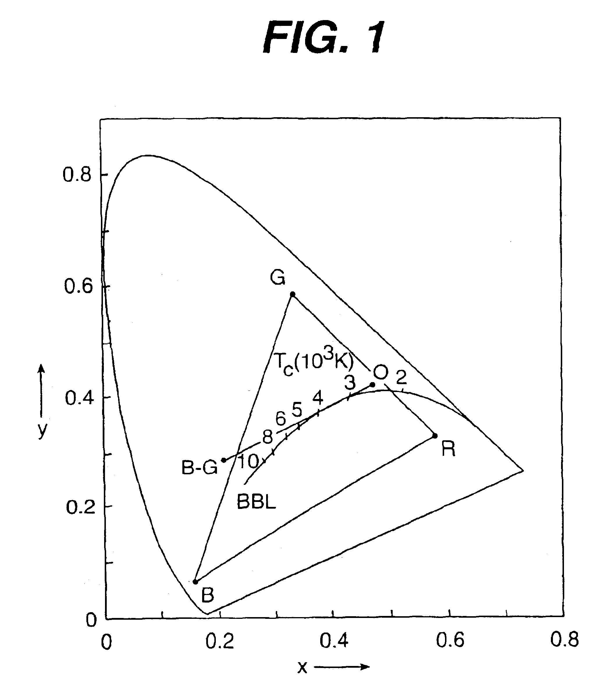
[0101]Three blends of three phosphors were prepared by the above mentioned process. The blend composition was varied based on the peak emission wavelength of the radiation source to be used with the blend. In general, for LED radiation sources having a peak emission or excitation wavelength between 370 and 405 nm, the amount of the first orange emitting phosphor in the blend increased while the amount of the second blue-green and third blue emitting phosphors decreased with increasing excitation wavelength. The excitation wavelength, the blend composition, the CIE color coordinates (ccx and ccy), the color temperature, the CRI and the efficacy of the blend are summarized in Table II, below.

[0102]

TABLE IIPHOSPHOREXCITA-BLENDColorEfficacyTION λ(WT %)ccxccyT (K)CRI(lm / W)380 mmSrP(57.5).4011.3807350770.5346.4BASI(21.5)SECA(21.0)390 mmSrP(61.4).3995.3830356570.7347.3BASI(19.4)SECA(19.2)405 mmSrP(73.7).3899.3791376772.3349.6BASI(12.1)SECA(14.2)

[0103]In the above table, the following abbre...

example 2

[0104]Three blends of four phosphors were prepared by the above mentioned process. The blend composition was varied based on the peak emission wavelength of the radiation source to be used with the blend. In general, for LED radiation sources having a peak emission or excitation wavelength between 370 and 405 nm, the amount of the first, second and third phosphors in the blend increased while the amount of the fourth phosphor decreased, with increasing excitation wavelength. The excitation wavelength, the blend composition, the CIE color coordinates (ccx and ccy), the color temperature, the CRI and the efficacy of the blend are summarized in Table III, below.

[0105]

TABLE IIIPHOSPHOREXCITA-BLENDColorEfficacyTION λ(WT %)ccxccyT (K)CRI(lm / W)380 mmSrP(12.7).4017.3835351993285BASI(10.0)SECA(7.4)MgF(69.9)390 mmSrP(17.6).4065.3793337493.5272.2BASI(11.8)SECA(9.0)MgF(61.6)405 mmSrP(41.5).3967.3743355791.3264.7BASI(14.2)SECA(12.8)MgF(31.5)

[0106]In the above table, the following abbreviations w...


PUM


Abstract

There is provided white light illumination system including a radiation source, a first luminescent material having a peak emission wavelength of about 575 to about 620 nm, a second luminescent material having a peak emission wavelength of about 495 to about 550 nm, which is different from the first luminescent material and a third luminescent material having a peak emission wavelength of about 420 to about 480 nm, which is different from the first and second luminescent materials. The LED may be a UV LED and the luminescent materials may be a blend of three or four phosphors. The first phosphor may be an orange emitting Eu2+, Mn2+ activated strontium pyrophosphate, Sr2P2O7:Eu2+, Mn2+. The second phosphor may be a blue-green emitting Eu2+ activated barium silicate, (Ba,Sr,Ca)2SiO4:Eu2+. The third phosphor may be a blue emitting SECA phosphor, (Sr,Ba,Ca)5(PO4)3Cl:Eu2+. Optionally, the fourth phosphor may be a red emitting Mn4+ activated magnesium fluorogermanate, 3.5MgO*0.5MgF2*GeO2:Mn4+. A human observer perceives the combination of the orange, blue-green, blue and/or red phosphor emissions as white light.

Description

[0001]This is a Divisional Application of application Ser. No. 09 / 570,932, filed May 15, 2000, which is incorporated by reference in its entirety and which has issued as U.S. Pat. No. 6,621,211 issued on Oct. 16, 2003.STATEMENT REGARDING FEDERALLY SPONSORED RESEARCH OR DEVELOPMENT[0002]The U.S. Government may have certain rights in this invention pursuant to grant number 70NANB8H4022 from the NIST.BACKGROUND OF THE INVENTION[0003]This invention relates generally to a white light illumination system, and specifically to a ceramic phosphor blend for converting UV radiation emitted by a light emitting diode (“LED”) to white light.[0004]White light emitting LEDs are used as a backlight in liquid crystal displays and as a replacement for small conventional lamps and fluorescent lamps. As discussed in chapter 10.4 of “The Blue Laser Diode” by S. Nakamura et al., pages 216-221 (Springer 1997), incorporated herein by reference, white light LEDs are fabricated by forming a ceramic phosphor l...

Claims


Application Information

Patent Timeline
IPC IPC(8): C09K11/77H01L33/00C09K11/64C09K11/73H01L33/50
CPCC09K11/7734H01L33/504Y02B20/181H01L2224/48091H01L2924/00014H01L2924/12044Y02B20/00C09K11/77342H01L2924/00G02F1/1335
Inventor SRIVASTAVA, ALOK MANICOMANZO, HOLLY ANNMCNULTY, THOMAS FRANCIS
Owner GE LIGHTING SOLUTIONS LLC
Why Eureka
Try Eureka